Image intensifier for improving detection performance of low-light level imaging system at normal temperature

A low-light imaging, image intensifier technology, applied in the direction of image conversion/image amplifying tube, electrode device and related components, screen tube, etc., can solve the problems affecting imaging quality, photon signal accumulation, electron accumulation, etc., to reduce escape Probability, clear imaging, effective accumulation effect

Inactive Publication Date: 2010-06-16
XIAN UNIV OF TECH
View PDF5 Cites 0 Cited by
  • Summary
  • Abstract
  • Description
  • Claims
  • Application Information

AI Technical Summary

Problems solved by technology

[0004] However, in order to achieve a higher low-light detection limit at room temperature, it is necessary to solve the problem of how to accumulate photon signals for a long time under low-light conditions.
At present, various low-light detection devices used, such as image-intensified ICCD (Intensified Charge Coupled Devices) and electron multiplied EMCCD (Electron Multiplying CCD), etc., although they each use different optical signal enhancement methods, but the optical signal However, the accumulation is completed through the long-term integration of the CCD. During this process, many factors such as thermal noise and bright light at the corners seriously affect the imaging quality. Therefore, the performance of the CCD directly limits the improvement of the low-light detection limit.
[0005] Although the various devices researched and developed above have the effect of strengthening and multiplying the electrons generated by the image intensifier, they have not been able to effectively accumulate the electrons, but only accumulate the photon signals for a long time through the CCD. Therefore, The low-light detection limit is largely limited by the 10 -6 lx increased to 10 -8 lx

Method used


Image

  • Image intensifier for improving detection performance of low-light level imaging system at normal temperature
  • Image intensifier for improving detection performance of low-light level imaging system at normal temperature
  • Image intensifier for improving detection performance of low-light level imaging system at normal temperature

Examples


Embodiment Construction

[0026] The present invention will be described in detail below in conjunction with the accompanying drawings and specific embodiments.

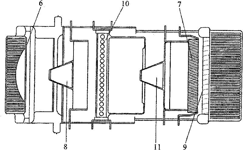
[0027] The structure of the image intensifier of the present invention, such as figure 1 shown. Including a photocathode 6 and a microchannel plate 7, between the photocathode 6 and the microchannel plate 7, from the photocathode 6 to the microchannel plate 7, a pre-electrostatic focusing electron optical system 8, a magnetic mirror array device 10 and a rear The electrostatic focusing electron optical system 11 is provided with a phosphor screen 9 on the outside of the microchannel plate 7 .

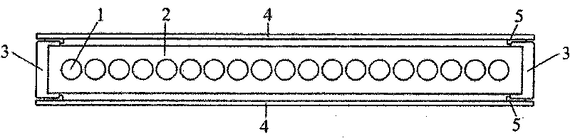
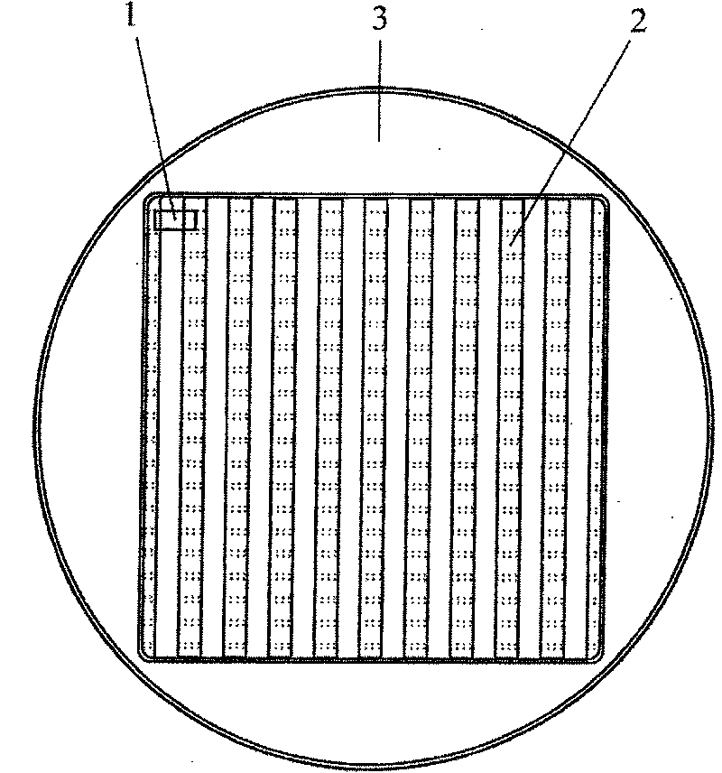
[0028] The structure of the magnetic mirror array device in the image intensifier of the present invention, such as figure 2 , image 3 , Figure 4 shown. It includes an annular support 3 with an outer circle and an inner square made of copper or ceramics. The inner wall of the support 3 is a bayonet. The square ring of the support 3 is provided ...


PUM


Abstract

The invention discloses an image enhancer for improving the detection performance of a low-light-level imaging system at normal temperature. The image enhancer comprises a photocathode and a microchannel plate which are arranged oppositely, a front electrostatic focusing electron optical system and a rear electrostatic focusing electron optical system which are sequentially arranged from the photocathode to the microchannel plate between the photocathode and the microchannel plate; a fluorescent screen which is arranged outside the microchannel plate, and a magnetic mirror array device which is arranged between the front electrostatic focusing electron optical system and the rear electrostatic focusing electron optical system. The image enhancer expands the effective utilization of low-light-level electron, reduces the escape probability of emergent electron at the photocathode in a magnetic mirror, more effectively accumulates optoelectronic signals at normal temperature and achievesthe enhancement to extremely weak light signals, thus achieving clear imaging at the illumination intensity of 10<-8>lx.

Description

technical field [0001] The invention belongs to the technical field of low-light imaging detection, and relates to an image intensifier for improving the detection performance of a low-light imaging system at normal temperature. Background technique [0002] Low-light night vision technology is widely used in transportation, television, communications, medicine and health, military and other fields. After nearly 30 years of rapid development, a detection limit of 10 has been developed -9 CCD (charge coupled device) camera with lx illuminance, German B&M Spectrum Company increased the detection limit of CCD camera to 10 at the temperature of -150°C -11 lx. Low-temperature low-light detection devices have a high signal-to-noise ratio, but they are bulky, technically difficult, and expensive, resulting in very limited application fields. Therefore, it is more practical to increase the detection limit of low-light imaging systems at room temperature. [0003] Our country has ...

Claims


Application Information

Patent Timeline
Patent Type & Authority Patents(China)
IPC IPC(8): H01J31/50H01J29/58
Inventor 郜海阳唐远河刘锴张瑞霞杨旭三赵高翔叶娜梁元李卿
Owner XIAN UNIV OF TECH
Why Eureka
Try Eureka