Rotary extrusion forming method of non-circular cross-section parts and equipment thereof

A non-circular cross-section, spinning forming technology, applied in the field of plastic processing, can solve the problems of reducing the mechanical properties of materials, affecting the normal use of parts, prolonging the processing cycle, etc., and achieve the effect of simple structure, improved production efficiency and short processing cycle

Inactive Publication Date: 2009-04-22
SOUTH CHINA UNIV OF TECH
View PDF0 Cites 16 Cited by
  • Summary
  • Abstract
  • Description
  • Claims
  • Application Information

AI Technical Summary

Problems solved by technology

This not only increases the process and prolongs the processing cycle, but also in the case of multiple varieties and small batches, the production cost will ine

Method used


Image

  • Rotary extrusion forming method of non-circular cross-section parts and equipment thereof
  • Rotary extrusion forming method of non-circular cross-section parts and equipment thereof
  • Rotary extrusion forming method of non-circular cross-section parts and equipment thereof

Examples


Embodiment 1

[0032] A spinning forming method of a non-circular section part of the present invention comprises the following steps:

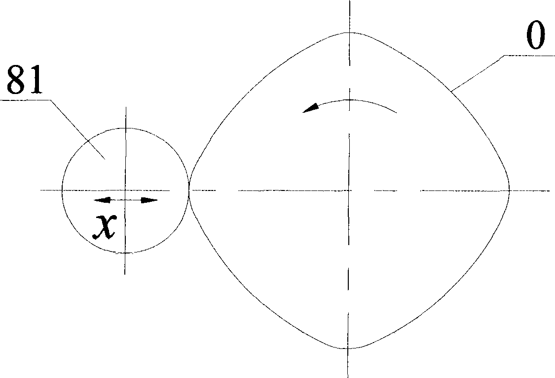
[0033] (1) if figure 1 As shown, according to the shape and size of the non-circular cross-section part O, set the feed trajectory of the rotary wheel (including the feed amount, the number of feeds of the rotary wheel when the main shaft rotates one revolution, etc.) and the feed speed on the console;

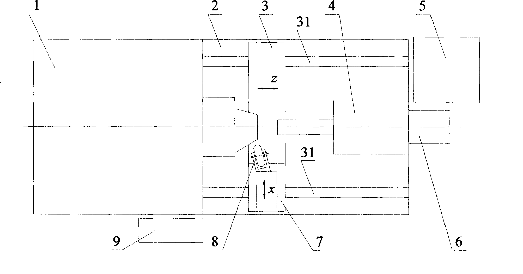
[0034] (2) To install the workpiece, that is, to clamp the workpiece on the shaft head of the main shaft first, and then drive the tail top device to clamp it by the hydraulic station, then start the servo motor feeding device, adjust the longitudinal moving platform so that the rotary wheel reaches the position close to the workpiece specified location;

[0035] (3) Start the spindle to rotate, and the spindle rotates to drive the workpiece to rotate;

[0036] (4) Simultaneously start the linear motor feed device to control the horizontal movement of the...

Embodiment 2

[0042] The spinning forming method of the non-circular cross-section parts of this embodiment is the same as that of Embodiment 1, and the working principle of the spinning forming equipment of the non-circular cross-section parts is also the same as that of Embodiment 1. Another method of the spinning forming equipment of the non-circular cross-section parts is a structure such as Figure 4 As shown, the difference from Embodiment 1 lies in the structure of the rotary wheel device 8 , and the addition of an inclined plane booster mechanism 10 between the linear motor feeding device 7 and the rotary wheel device 8 .

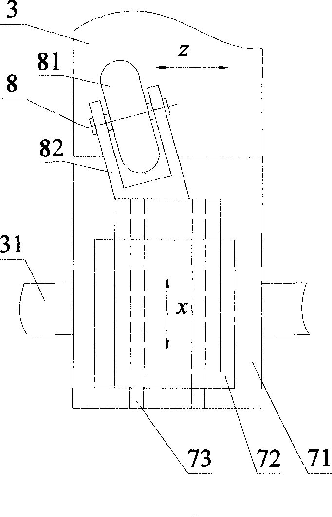
[0043] Such as Figure 5 As shown, between the linear motor feeding device 7 and the rotary wheel device 8, an inclined plane booster mechanism 10 is added, wherein the inclined plane booster mechanism 10 includes an inclined plane propulsion block 101 and a roller 102; the rotary wheel device 8 includes a rotary wheel seat 83, Horizontal linear guide rail 84, r...


PUM


Abstract

The invention provides a spin forming method for non-circular section parts and equipment thereof. The method comprises the following steps: after a workpiece is mounted, a main shaft starts to drive the workpiece to rotate, and a rotary wheel device transversely feeds; within one-circle rotation of the main shaft, the rotary wheel device quickly moves forward and backward for a plurality of times, a coordinate relationship is maintained between rotary angles of the main shaft; at the same time, a platform is longitudinally moved to drive the rotary wheel to feed longitudinally, so that the workpiece, after spin forming, is formed into non-circular section parts; the equipment consists of a machine tool and a control platform circuit which are connected with each other, the machine tool comprises a main spindle box, a machine tool body, a longitudinal motion platform, a tail-top device, a servo motor feeding device, a hydraulic station, a linear motor feeding device and a rotary wheel device, the main spindle box and the tail-top device are coaxially arranged on both ends of the machine tool body, the hydraulic station is connected with the tail-top device by an oil pipe, the servo motor feeding device is arranged on one part of the machine tool body, the longitudinal motion platform is arranged in the machine tool body, both ends of the longitudinal motion platform are provided with longitudinal straight line guide rails, and the linear motor feeding device driving the rotary wheel device is arranged on one side of the longitudinal motion platform.

Description

technical field [0001] The invention relates to the technical field of plastic processing, in particular to a spinning forming method and equipment for parts with non-circular cross-sections. Background technique [0002] The traditional spinning forming methods can be divided into two categories, namely ordinary spinning (spinning without constant thinning) and powerful spinning (spinning with thinning). During ordinary spinning or powerful spinning, the workpiece is clamped on the spindle of the machine tool, and rotates with the spindle of the machine tool, and the spinning wheel moves radially and axially along the axis of the workpiece, so that it can be processed into various shapes of axisymmetric Thin-walled hollow parts (uniaxial spinning parts). [0003] In recent years, a new spinning forming method has emerged. During spinning, the workpiece is clamped on a worktable that can simultaneously or separately move longitudinally and laterally along the machine tool s...

Claims


Application Information

Patent Timeline
IPC IPC(8): B21D22/14
Inventor 夏琴香程秀全
Owner SOUTH CHINA UNIV OF TECH
Why Eureka
Try Eureka