Method and apparatus for single-stage mixing cryogen refrigerating cycle liquefied natural gas

A technology of liquefied natural gas and mixed refrigerant, applied in refrigeration and liquefaction, liquefaction, gas fuel and other directions, can solve the problems of increased production cost, increased input cost, increased number of equipment, etc., to reduce equipment investment, reduce production costs, The effect of simplifying the looping process and operational control

Inactive Publication Date: 2009-04-22
CHENGDU SEPMEM SCI & TECH
View PDF0 Cites 32 Cited by
  • Summary
  • Abstract
  • Description
  • Claims
  • Application Information

AI Technical Summary

Problems solved by technology

However, its cooler is placed on the ground, and after the mixed refrigerant compressed by the compressor enters the cooler, it is partially liquefied in the cooler to generate a gas-liquid two-phase (in the pipeline after the cooler); in order to solve the problem of mixed cold For the problem of two-phase flow of refrigerant gas and liquid, this technology still has a gas-liquid separator to separate the gas and liquid after the cooler, and pumps the separated liquid re

Method used


Image

  • Method and apparatus for single-stage mixing cryogen refrigerating cycle liquefied natural gas
  • Method and apparatus for single-stage mixing cryogen refrigerating cycle liquefied natural gas
  • Method and apparatus for single-stage mixing cryogen refrigerating cycle liquefied natural gas

Examples


Example Embodiment

[0031] Example 1

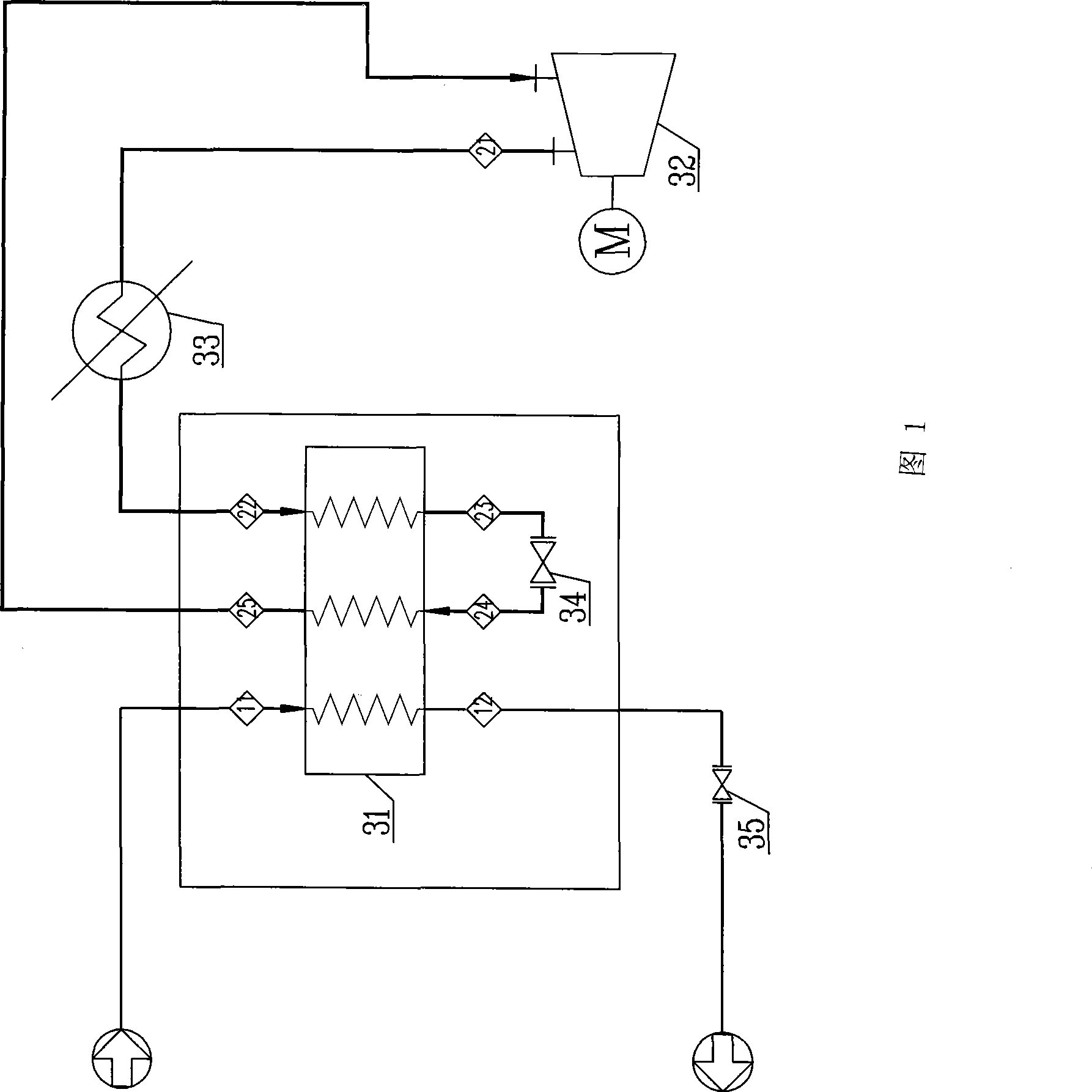
[0032] The schematic diagram of the device (without heavy hydrocarbon separation module) used in this embodiment is shown in Figure 1. It mainly includes a refrigeration cycle system and a natural gas liquefaction system. The refrigeration cycle system consists of a compressor 32, a cooler 33, and a cold box (the main equipment is The heat exchanger 31), the mixed refrigerant throttle valve 34 (located in the cold box), etc. are connected by pipes to form a closed refrigeration cycle system; the heat exchanger 31 in the cold box also passes through the natural gas throttle valve 35, etc. The natural gas inlet and outlet pipelines are connected to form a natural gas liquefaction system; the cooler 33 is located at the top of the cold box (outside the cold box).

[0033] The mixed refrigerant used is composed of 5% N 2 , 35% CH 4 , 26% C 2 H 4 , 16% C 3 H 8 , 18% C 5 H 12 composition.

[0034] The method for single-stage mixed refrigerant refrigeration cycle lique...

Example Embodiment

[0040] Example 2

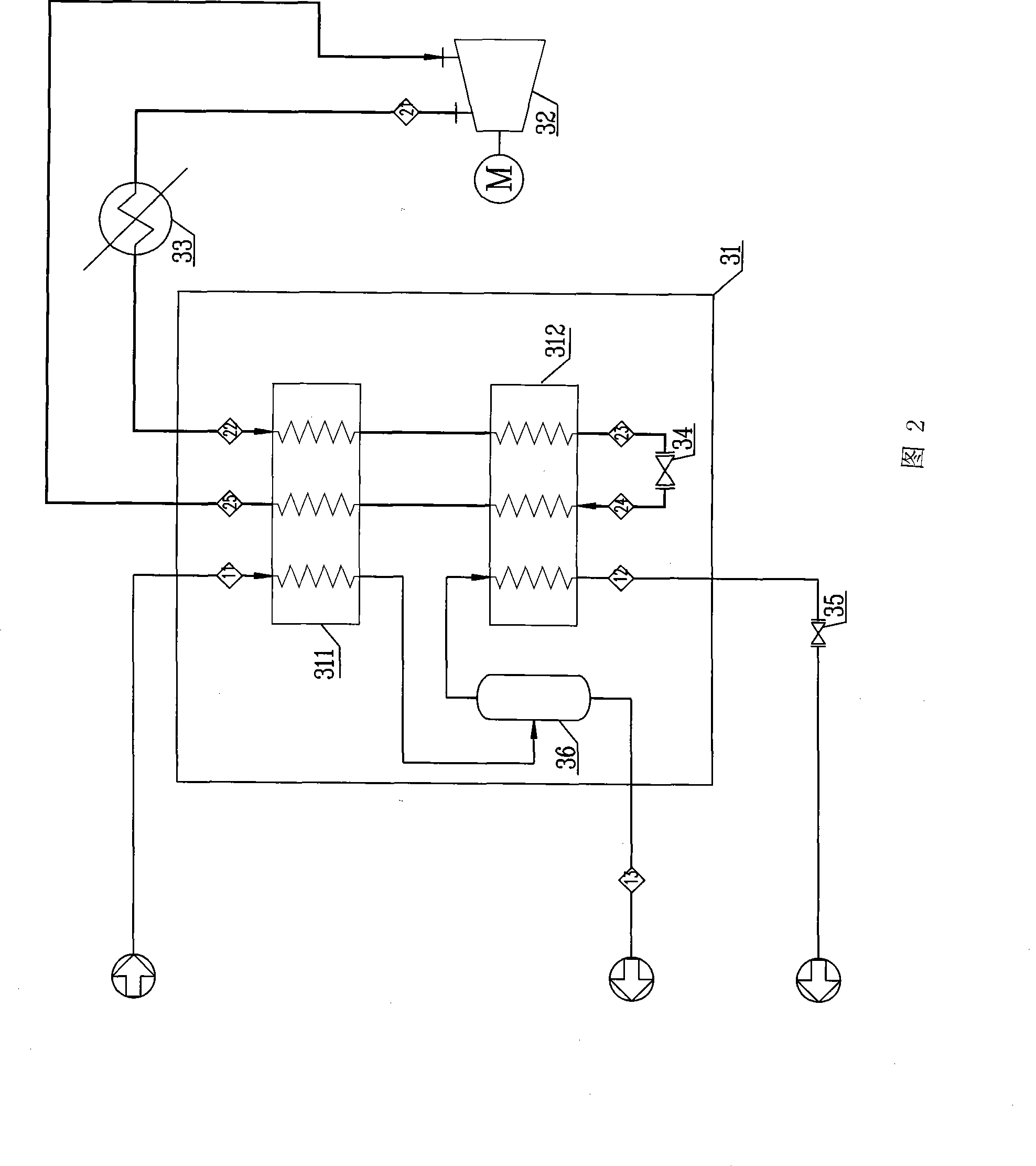
[0041] The schematic diagram of the device (with heavy hydrocarbon separation module) used in this embodiment is shown in Figure 2. It mainly includes a refrigeration cycle system and a natural gas liquefaction system. The refrigeration cycle system consists of a compressor 32, a cooler 33, and a cold box (the main equipment is a The heat exchanger, including the pre-cooling heat exchanger 311 and the main cooling heat exchanger 312), the mixed refrigerant throttle valve 34 (located in the cold box), etc. are connected by pipes to form a closed refrigeration cycle system; the pre-cooling in the cold box The cold heat exchanger 311 and the main cold heat exchanger 312, as well as the heavy hydrocarbon separator 36, the natural gas throttle valve 35, etc., are connected to form a natural gas liquefaction system through natural gas inlet and outlet pipelines.

[0042] The mixed refrigerant used is composed of 5% N 2 , 35% CH 4 , 26% C 2 H 4 , 16% C 3 H 8 , 18% C 5 ...

Example Embodiment

[0049] Example 3

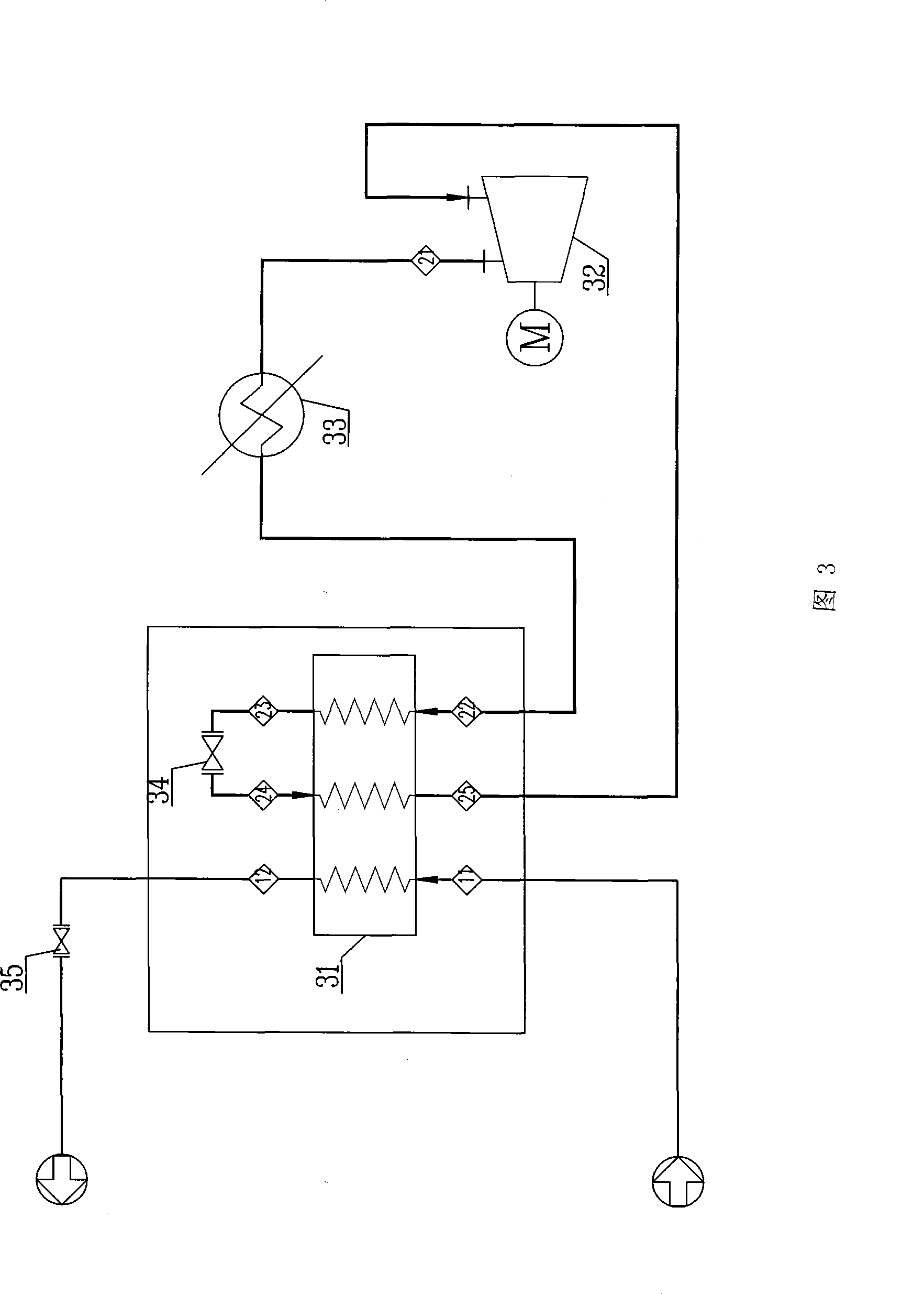
[0050] The schematic diagram of the device (without heavy hydrocarbon separation module) used in this embodiment is shown in Figure 3. It mainly includes a refrigeration cycle system and a natural gas liquefaction system. The refrigeration cycle system consists of a compressor 32, a cooler 33, and a cold box (the main equipment is The heat exchanger 31), the mixed refrigerant throttle valve 34 (located in the cold box), etc. are connected by pipes to form a closed refrigeration cycle system; the heat exchanger 31 in the cold box also passes through the natural gas throttle valve 35, etc. The natural gas inlet and outlet pipelines are connected to a natural gas liquefaction system; among them, the pipeline for natural gas entering and exiting the cold box adopts a bottom-in-top-out connection, and the pipeline for the mixed refrigerant to enter and exit the cold box is connected with the cold box in a bottom-in and bottom-out manner.

[0051] The mixed refrigeran...


PUM


Abstract

The invention discloses a method for liquefying natural gas by the refrigeration cycle of a single stage mixed refrigerant, which comprises the following steps: raw natural gas passes through a heat exchanger in an ice chest to exchange heat with the mixed refrigerant, and is cooled and liquefied; wherein, in sequence, the mixed refrigerant is first pressurized by a compressor, cooled by a cooler, directly enters the heat exchanger to be precooled without gas-liquid separation, goes out of the heat exchanger for depressurization and temperature reduction and then returns to the heat exchanger to exchange the heat of the natural gas and liquefy the natural gas, as well as is vaporized to gaseous mixed refrigerant and returns to the compressor for the next cycle; by reducing the outlet pressure of the compressor, or boosting the position of the outlet cooler of the compressor or using a way that the mixed refrigerant goes in and out of the ice chest both from the lower part, the method solves the problem of two phase flow of gas and liquid; can reduce the investment of the equipment such as a gas-liquid separator, a pump and the like, simplify the cycle process and operation control and reduce the manufacture cost as well. The invention also discloses a device applied to the method.

Description

technical field [0001] The invention belongs to the technical field of liquefaction of natural gas, coal bed methane or other methane-rich gases, and in particular relates to a single-stage mixed refrigerant refrigeration cycle liquefaction method and device. Background technique [0002] The main component of natural gas and coalbed methane is methane, which cannot be liquefied at room temperature only by pressurization. It needs to be liquefied by natural gas liquefaction process. For example, methane under normal pressure is liquefied into LNG (liquefied natural gas) at -162°C. Its volume is only 1 / 625 of the original gas state, and its density is more than 600 times that of methane in the standard state. , 45% of water, volumetric energy density of 72% of gasoline. Because of its clean burning quality and ease of use, it is a high-quality industrial and domestic fuel, and at the same time it is very convenient for transportation and storage. [0003] At present, common...

Claims


Application Information

Patent Timeline
IPC IPC(8): F25J1/02C10L3/10
CPCF25J1/0022F25J1/0052F25J1/0212F25J1/0258F25J1/0259F25J1/0296F25J2220/64
Inventor 张惊涛杨勇刚
Owner CHENGDU SEPMEM SCI & TECH
Why Eureka
Try Eureka