Picopulse optical fiber laser

A fiber laser, picosecond pulse technology, applied in the laser field, can solve the problem of low repetition frequency of picosecond light pulse, and achieve the effect of high repetition frequency

Inactive Publication Date: 2009-04-22
BEIHANG UNIV
View PDF0 Cites 9 Cited by
  • Summary
  • Abstract
  • Description
  • Claims
  • Application Information

AI Technical Summary

Problems solved by technology

[0004] The above prior art has at least the following disadvantages: the pulse period depends on th

Method used


Image

  • Picopulse optical fiber laser
  • Picopulse optical fiber laser
  • Picopulse optical fiber laser

Examples


Embodiment Construction

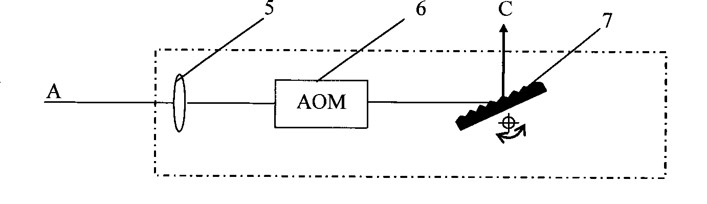
[0013] A preferred embodiment of the picosecond pulsed fiber laser of the present invention includes a main resonant cavity and an external cavity feedback part.

[0014] Among them, the external cavity feedback part includes AOM (acousto-optic modulator), AOM adopts Raman-Nath (Raman-Ness) diffraction, in the generated diffracted light, zero-order light output, any order of high-level light is fed back to in the main resonator. The laser output from the main resonator can be vertically incident on the crystal surface of the AOM after being collimated by the collimating lens. The high-level light can be any level of 2-level light, 3-laser to 5-level light, or higher-level diffracted light. The modulation frequency of the AOM may be greater than or equal to 40MHz.

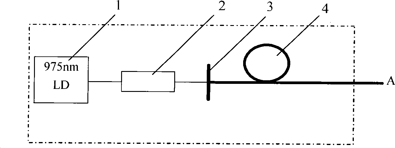
[0015] Such as figure 1 As shown, the main resonant cavity may include a dichroic mirror 3 and an ytterbium-doped double-clad fiber 4 .

[0016] In a specific embodiment, the main resonator may include a semicon...


PUM


Abstract

The invention discloses a picosecond pulse optical fibre laser which comprises a main cavity resonator and an outer cavity feedback part. A semiconductor laser is adopted as a pumping source; a dichroic mirror and double envelope optical fibre mixing with ytterbium form the main cavity resonator which is coupled to an outer cavity through a collimating lens; a acoustooptic modulator AOM in the outer cavity adopts Raman-Nath diffraction; and a blazed grating outputs zero-level diffraction light generated by a signal light and feeds back any level light in high-level light to the cavity resonator. The invention has simple structure and high cost performance, can realize wide-tune, narrow-line-width and stable picosecond pulse laser output and can be widely applied to the fields of laser processing, laser medical treatment, laser marking, seed light source, etc.

Description

technical field [0001] The invention relates to a laser technology, in particular to a picosecond pulse fiber laser. Background technique [0002] Picosecond (ps) pulsed Ytterbium-doped double-clad fiber lasers with wide tuning and narrow linewidth have great application value in laser processing, seed light sources for terahertz waves and femtosecond lasers, etc. Picosecond pulsed fiber lasers have incomparable advantages such as low threshold, low noise, high signal-to-noise ratio, miniaturization, and no need for refrigeration. Femtosecond laser seed source is a very attractive source. [0003] Among the picosecond pulsed fiber lasers in the prior art, one is an actively mode-locked fiber laser, and the AOM (acousto-optic modulator) uses Bragg (Bragg) diffraction. At this time, only zero-order light and one-order light appear after AOM diffraction. The first-order light is fed back into the cavity through the grating, and the zero-order light is output. [0004] The ab...

Claims


Application Information

Patent Timeline
IPC IPC(8): H01S3/067H01S3/08
Inventor 胡姝玲胡汉伟魏利民张晓青张春熹
Owner BEIHANG UNIV
Why Eureka
Try Eureka