Field emission generating set

A field emission and power generation device technology, applied in the direction of generators/motors, circuits, discharge tubes, etc., can solve problems such as inability to guarantee, unable to meet the needs of society, limited fossil fuels, etc., to achieve easy operation control and low energy consumption inhibitory effect

Inactive Publication Date: 2009-04-22
赤松则男
View PDF5 Cites 1 Cited by
  • Summary
  • Abstract
  • Description
  • Claims
  • Application Information

AI Technical Summary

Problems solved by technology

[0003] In the above-mentioned power generation using fossil fuels, there is a problem that the fossil fuels used as raw materials are limited, so they will be exhausted sooner or later, and the needs of society cannot be met.
[0004] In addition, in the above-mentioned power generation using natural energy such as solar energ

Method used


Image

  • Field emission generating set
  • Field emission generating set
  • Field emission generating set

Examples


Embodiment Construction

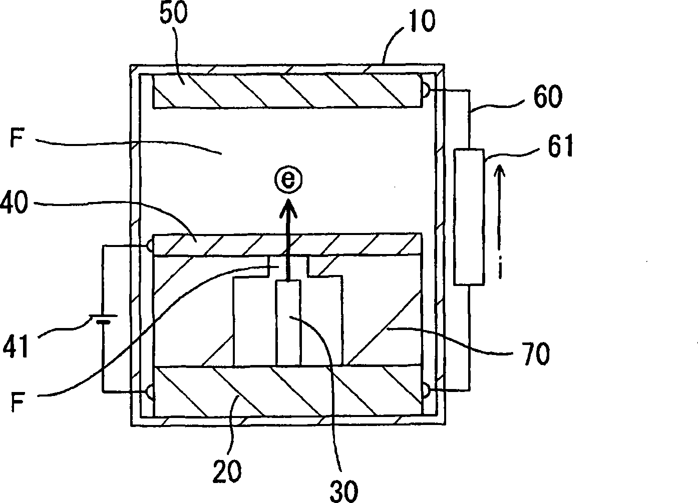
[0119] refer to figure 1 , the field emission power generation device according to the first embodiment of the present invention will be described.

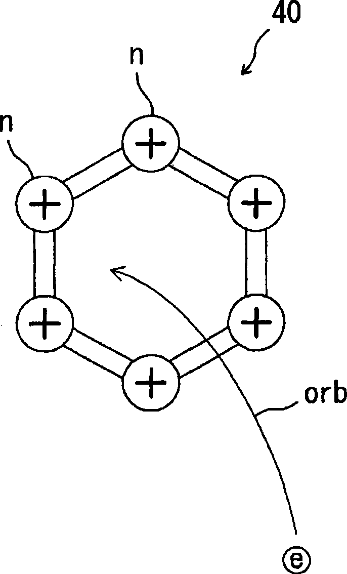
[0120] In the first embodiment, the field-emitted electrons e pass through the electron attraction emitter electrode 40 due to the tunneling phenomenon, and reach the electron acceptor 50 .

[0121] figure 1 This is a schematic cross-sectional structure diagram of a field emission power generation device.

[0122] An electron donor 20 , an electron emission port 30 , an electron attraction emission electrode 40 , and an electron acceptor 50 are provided in the vacuum container 10 .

[0123] In addition, an electron attraction emission power source 41 and a power extraction circuit 60 are provided outside the vacuum container 10 .

[0124] The above-mentioned vacuum container 10 is a container whose inside is in a vacuum or sufficiently depressurized state, and the type of material is not particularly limited.

[0125] The abo...


PUM


Abstract

Based on a new concept, which is different from the conventional electric-power generating method, a stable electric power generation is enabled that requires less energy, exhibits a high efficiency and cleanness, and has no fear of exhaustion. There are included an electron supplier (20) that holds free electrons; an electron emitting port (30) that is located at the electron supplier (20) in such a manner that it is electrically conductive with the electron supplier (20); an electron pulling-in/releasing electrode (40) that is opposed to the electron emitting port (30) with an electric insulation field (F) intervening therebetween and to which electric fields are applied, thereby causing the electron pulling-in/releasing electrode (40) to pull in and release electrons; an electron acceptor (50) that receives the electrons released by the electron pulling-in/releasing electrode (40); ; and an electron absorption inhibiting means that inhibits the electron pulling-in/releasing electrode (40) from absorbing the electrons emitted from the electron emitting port (30). A positive voltage is applied to the electron pulling-in/releasing electrode (40), thereby causing the electron emitting port (30) to field emit electrons, which are then received by the electron acceptor (50) for collection.

Description

technical field [0001] The present invention relates to a power generation device utilizing field emission (radiation). Background technique [0002] In power generation as a method of obtaining electric energy, power generation utilizing natural energy, such as solar power generation and tidal power generation, is known in addition to hydroelectric power generation and wind power generation that have been performed since ancient times. Thermal power generation using fossil fuels and atomic power generation using atomic energy are also known. [0003] In the above-mentioned power generation using fossil fuels, there is a problem that the fossil fuels used as raw materials are limited, so they will be exhausted sooner or later and cannot meet the needs of society. [0004] In addition, in the above-mentioned power generation using natural energy such as solar energy or wind energy, the supply of solar energy and wind energy as the natural energy used depends on natural condi...

Claims


Application Information

Patent Timeline
IPC IPC(8): H02N11/00
CPCH01J45/00H01J3/021
Inventor 赤松则男
Owner 赤松则男
Why Eureka
Try Eureka