Semi-automatic welding method of metal flux cored filler rod conduit root

A semi-automatic welding and metal powder core technology, applied in welding equipment, metal processing equipment, tubular objects, etc., can solve the problems of difficult on-site maintenance, unfavorable on-site maintenance, high equipment cost, reduce labor intensity, improve welding production efficiency, The effect of reducing operating costs

Active Publication Date: 2009-04-29
BC P INC CHINA NAT PETROLEUM CORP +1
View PDF0 Cites 28 Cited by
  • Summary
  • Abstract
  • Description
  • Claims
  • Application Information

AI Technical Summary

Problems solved by technology

[0003] (1) Internal welding machine: This welding machine is the product of the combination of automatic welding and internal counterparts. The root welding is completed by six automatic welding torch heads in the pipe at the same time. The technology is relatively mature, and the speed is the fastest and the quality is the best. The cost is very high, and the structure is complex, and on-site maintenance is difficult;
[0004] (2) Semi-automatic downward root welding with solid welding wire (such as STT root welding equipment in the United States and PWT root welding equipment in Italy): This technology is relatively mature, but it has strict requirements on the gap between the pipe joints and the amount of misalignment, and it is very easy Unfused defects on the side wall are generated. Once the gap is greater than 1mm, arc breaks will occur, and the cost is high and the structure is complicated, which is not conducive to on-site maintenance;

Method used


Image

  • Semi-automatic welding method of metal flux cored filler rod conduit root
  • Semi-automatic welding method of metal flux cored filler rod conduit root
  • Semi-automatic welding method of metal flux cored filler rod conduit root

Examples


Embodiment Construction

[0024] The present invention is not limited by the following embodiments, and specific implementations can be determined according to the above technical solutions and actual conditions of the present invention.

[0025] The present invention will be further discussed below in conjunction with the best embodiment:

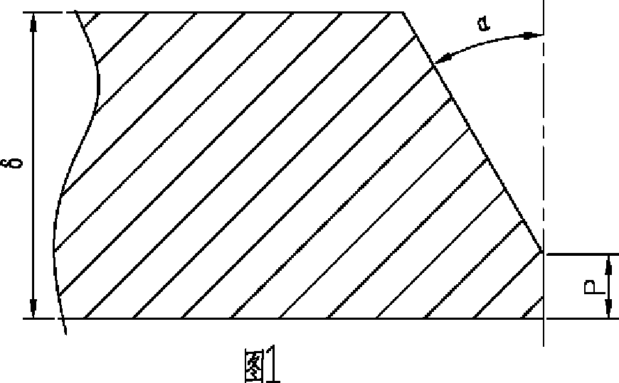
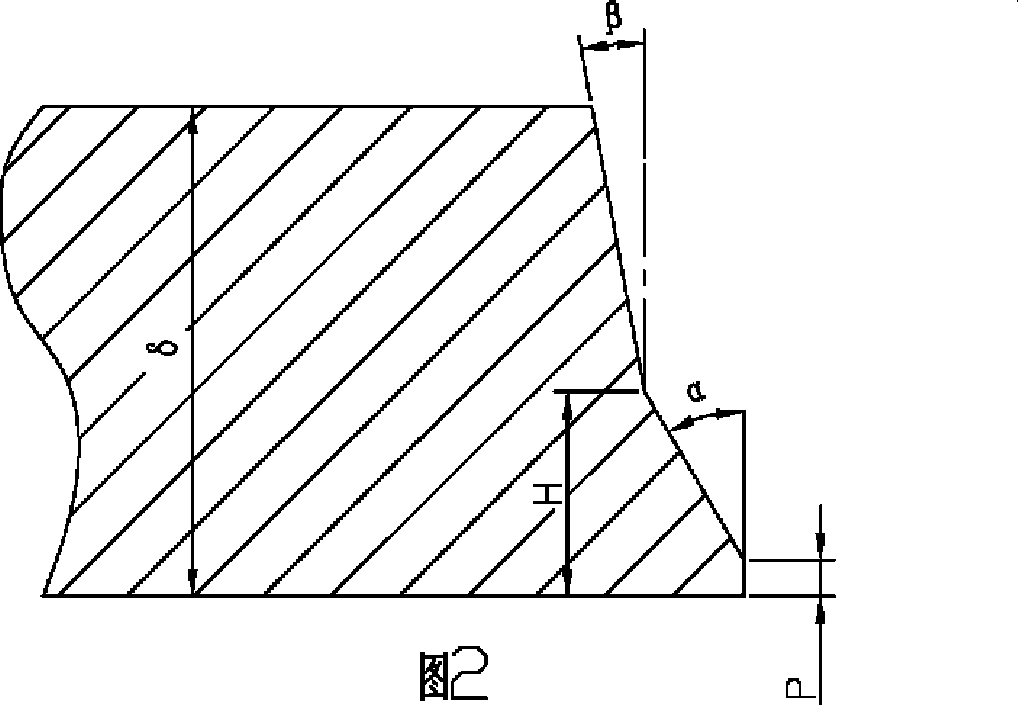
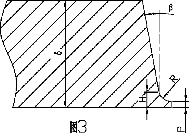
[0026] The semi-automatic welding method for pipe root welding with metal powder cored wire is carried out according to the following steps: it includes welding nozzle pretreatment, root welding layer welding, hot welding layer welding, filling layer welding and capping layer welding. The following steps are carried out: using metal powder cored welding wire and short arc control technology, namely RMD, plus shielding gas for welding of all positions of the root bead of the pipeline, the welding process parameters of the root weld layer are as follows: using semi-automatic downward welding process, welding The current is 140A to 200A, the welding voltage is 15V to 18V,...


PUM

PropertyMeasurementUnit
verticalityaaaaaaaaaa
thicknessaaaaaaaaaa
diameteraaaaaaaaaa

Abstract

The invention relates to the technical field of welding of a long distance pipeline and is a semi-automatic welding method of root welding of a pipeline with metal powder core welding wire; the root welding layer welding is carried out as follows: the metal powder core welding wire and short arc control technology are adopted, protective gases are added to carry out welding of root welding bead of full position; the welding parameters are as follows: welding current is 140A to 200A; the welding voltage is 15V to 18V; the welding speed is 16cm / min to 26cm / min; the wire feed speed is 350cm / min to 500cm / min; the wire extension is 8mm to 12mm; and the pendulum deflection is based on that weld metal is deposited to the edge of a welding pipeline. The method solves the bottleneck problem of restraining the flow construction operation of the semi-automatic welding, effectively solves the problems of undercut, depression and the like of the back surface of welding seams of circular welding joints, reduces the cost of cleaning of the surface of welding pipelines, reduces the labor intensity of workers, increases the thickness of deposited metal, reduces the welding layers, greatly improves welding production efficiency, obtains high-quality welding seams and improves the welding speed, can reduce one third time of welding compared with manual welding and reduces the operation cost.

Description

1. Technical Field: [0001] The invention relates to the technical field of welding of long-distance pipelines, and is a semi-automatic welding method for root welding of metal powder-cored wire pipelines. 2. Background technology: [0002] At present, the filling welding and cap welding processes used in the construction of long-distance pipeline projects in China are similar, but the root welding processes are quite different. There are three main types: [0003] (1) Internal welding machine: This welding machine is a combination of automatic welding and internal pairing device. Six automatic welding torch heads can complete root welding at the same time. The technology is mature, and the speed is the fastest and the quality is the best, but the equipment The cost is very high, and the structure is complicated, and on-site maintenance is difficult; [0004] (2) Semi-automatic downward root welding with solid core wire (such as STT root welding equipment in the United States, PWT...

Claims


Application Information

Patent Timeline
Patent Type & Authority Applications(China)
IPC IPC(8): B23K9/16B23K9/095B23K9/235B23K33/00B23K101/06
Inventor 黄军平曾君王新王振平
Owner BC P INC CHINA NAT PETROLEUM CORP
Why Eureka
Try Eureka