Torch and contact tip for gas metal arc welding

A gas shielding and contact tip technology, which is applied in arc welding equipment, metal processing equipment, gas fuel burners, etc., can solve the problem of hindering the smooth supply of welding wire into the welding pool, disturbing the quality of welding arc welding, hindering the flow of shielding gas, etc. question

Inactive Publication Date: 2009-04-29
GM GLOBAL TECH OPERATIONS LLC
View PDF0 Cites 31 Cited by
  • Summary
  • Abstract
  • Description
  • Claims
  • Application Information

AI Technical Summary

Problems solved by technology

[0003] One problem with the gas metal arc welding methods described above is that weld spatter can build up on the nozzle and contact tip, thereby impeding the flow of shielding gas, preventing the smooth feeding of the welding wire into the weld pool and / or interfering with the arc and other impairments to weld quality. influences

Method used


Image

  • Torch and contact tip for gas metal arc welding
  • Torch and contact tip for gas metal arc welding
  • Torch and contact tip for gas metal arc welding

Examples


Embodiment Construction

[0014] The following description of specific exemplary embodiments is exemplary in nature and is not intended to limit the invention and its application or uses.

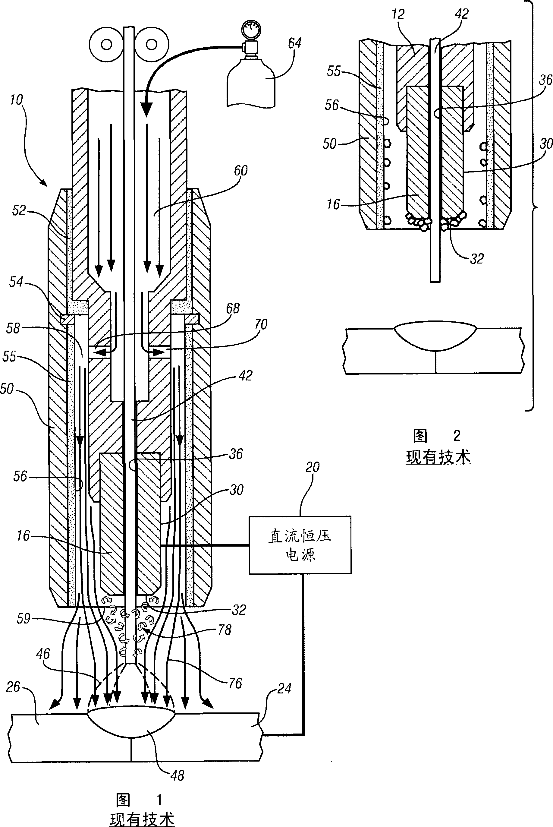
[0015] Fig. 1 is an overall sectional view of a conventional welding torch used for gas metal arc welding. The welding torch, indicated generally at 10 , includes a housing 12 in which a contact tip 16 is mounted. Housing 12 may be attached to the handle of a welding torch, not shown, and operated by a welder, or housing 12 may be operated by a robot or other manipulator. As shown in FIG. 1 , housing 12 supports contact tip 16 over workpieces 24 and 26 to be welded together. Contact tip 16 is generally cylindrical and has a cylindrical outer surface 30 and a circular end surface 32 . The electrode hole 36 penetrates the contact tip 16 in the axial direction. Contact tip 16 is typically made of a conductive material such as copper. The contact tip 16 is electrically connected to a welding power source 20 .

[00...


PUM


Abstract

A torch for gas metal arc welding includes a torch housing and a contact tip mounted on the housing and having an electrode bore through which electrode wire is fed. A nozzle mounted on the housing surrounds the contact tip to define an annular gas passage between the contact tip and the inside of the nozzle. A shielding gas inlet communicates a shielding gas into the annular gas passage so that the shielding gas flows out of the nozzle. A plurality of auxiliary flow passages are provided in the contact tip, and have open ends arranged around the electrode bore. The auxiliary flow passages communicate with the gas inlet and surround the electrode wire with an auxiliary flow of shielding gas that is closer to the electrode wire than the shielding gas flow that is provided through the annular gas passage between the contact tip and the nozzle.

Description

technical field [0001] The present invention relates to a welding torch for gas metal arc welding, and more particularly to a welding torch and contact tip that improves the flow of shielding gas to reduce weld spatter on the welding torch. Background technique [0002] Gas metal arc welding is an arc welding method in which a continuous consumable electrode wire is fed through the contact tip of a welding torch. The nozzle surrounds the contact tip. A constant voltage DC power supply creates an arc between a continuously supplied wire electrode and the workpiece to form a weld puddle. A shielding gas, such as argon, is piped between the nozzle and the contact tip through the torch to protect the weld pool from atmospheric gases such as nitrogen and oxygen, which can cause fusion defects, porosity and embrittlement of the weld metal. [0003] One problem with the gas metal arc welding methods described above is that weld spatter can build up on the nozzle and contact tip, ...

Claims


Application Information

Patent Timeline
Patent Type & Authority Applications(China)
IPC IPC(8): B23K9/28B23K9/26B23K9/16
CPCF23D14/40F23D14/54B23K9/173
Inventor A·D·哈哈列夫
Owner GM GLOBAL TECH OPERATIONS LLC
Why Eureka
Try Eureka