Heating resistor element, manufacturing method for the same, thermal head, and printer

A technology for heating resistors and manufacturing methods, applied in printing and other directions, can solve problems such as tailing and print quality degradation, and achieve the effects of suppressing heat accumulation, preventing print quality degradation, and preventing degradation.

Inactive Publication Date: 2009-04-29
SEIKO INSTR INC
View PDF1 Cites 6 Cited by
  • Summary
  • Abstract
  • Description
  • Claims
  • Application Information

AI Technical Summary

Problems solved by technology

Therefore, if printing is performed for a long time, the hollow portion becomes a heat source, which causes a problem of degrad...

Method used


Image

  • Heating resistor element, manufacturing method for the same, thermal head, and printer
  • Heating resistor element, manufacturing method for the same, thermal head, and printer
  • Heating resistor element, manufacturing method for the same, thermal head, and printer

Examples


Embodiment Construction

[0041]The heating resistance element 1, the manufacturing method thereof, the thermal head 2 and the thermal printer (printer) 3 based on the embodiment of the present invention are described below with reference to FIGS. Figure 7 to describe.

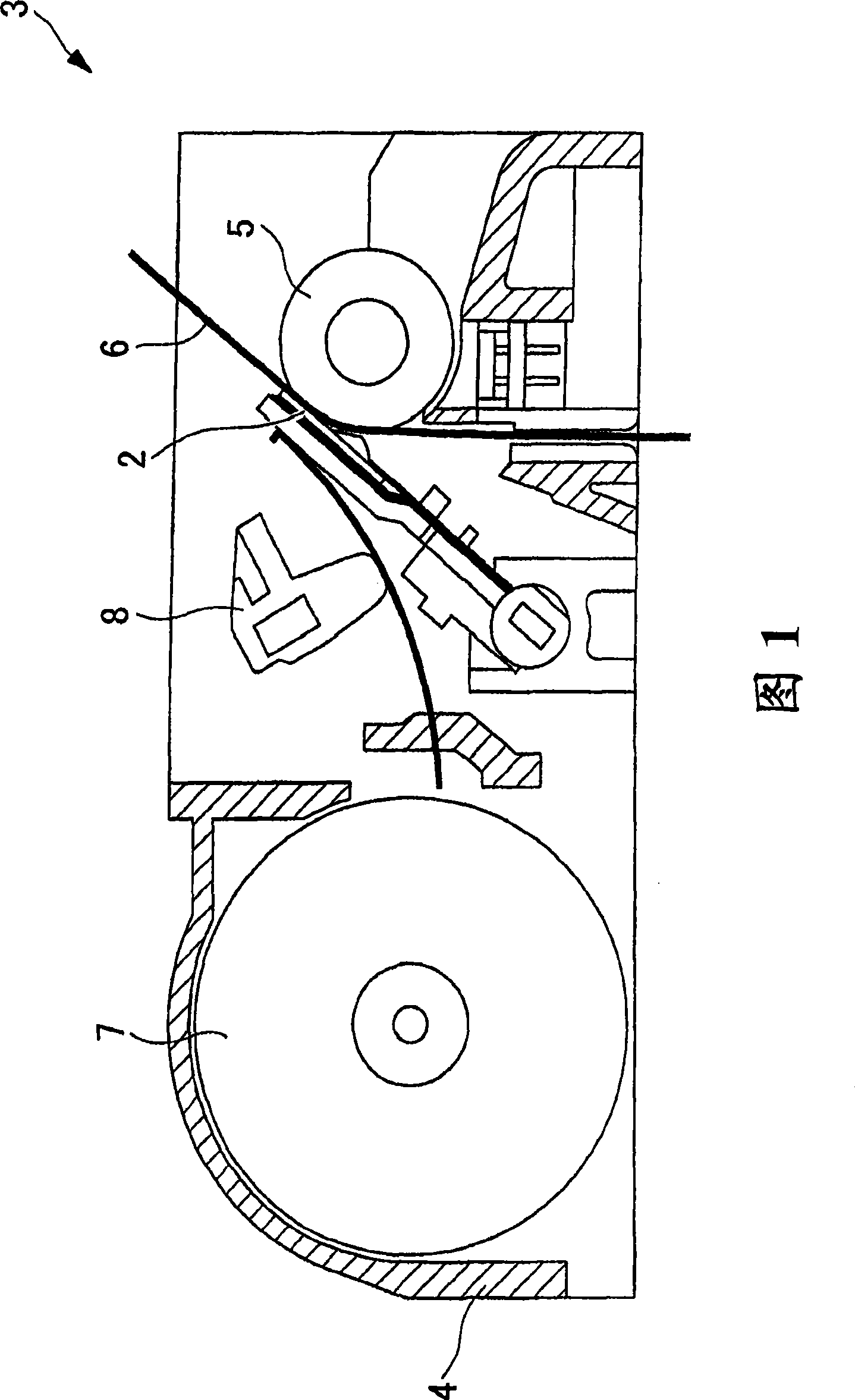
[0042] The heating resistance element 1 based on this embodiment is used in the thermal head 2 of the thermal printer 3 shown in FIG. 1 .

[0043] The thermal printer 3 includes a body frame 4, a platen roller 5 arranged horizontally, a thermal head 2 arranged to face the outer periphery of the platen roller 5, and a thermal head 2 between the platen roller 5 and the heat sensitive printer. A paper feeding mechanism 7 for feeding thermal paper 6 between the heads 2, and a pressing mechanism 8 for pressing the thermal head 2 against the thermal paper 6 with a predetermined pressing force.

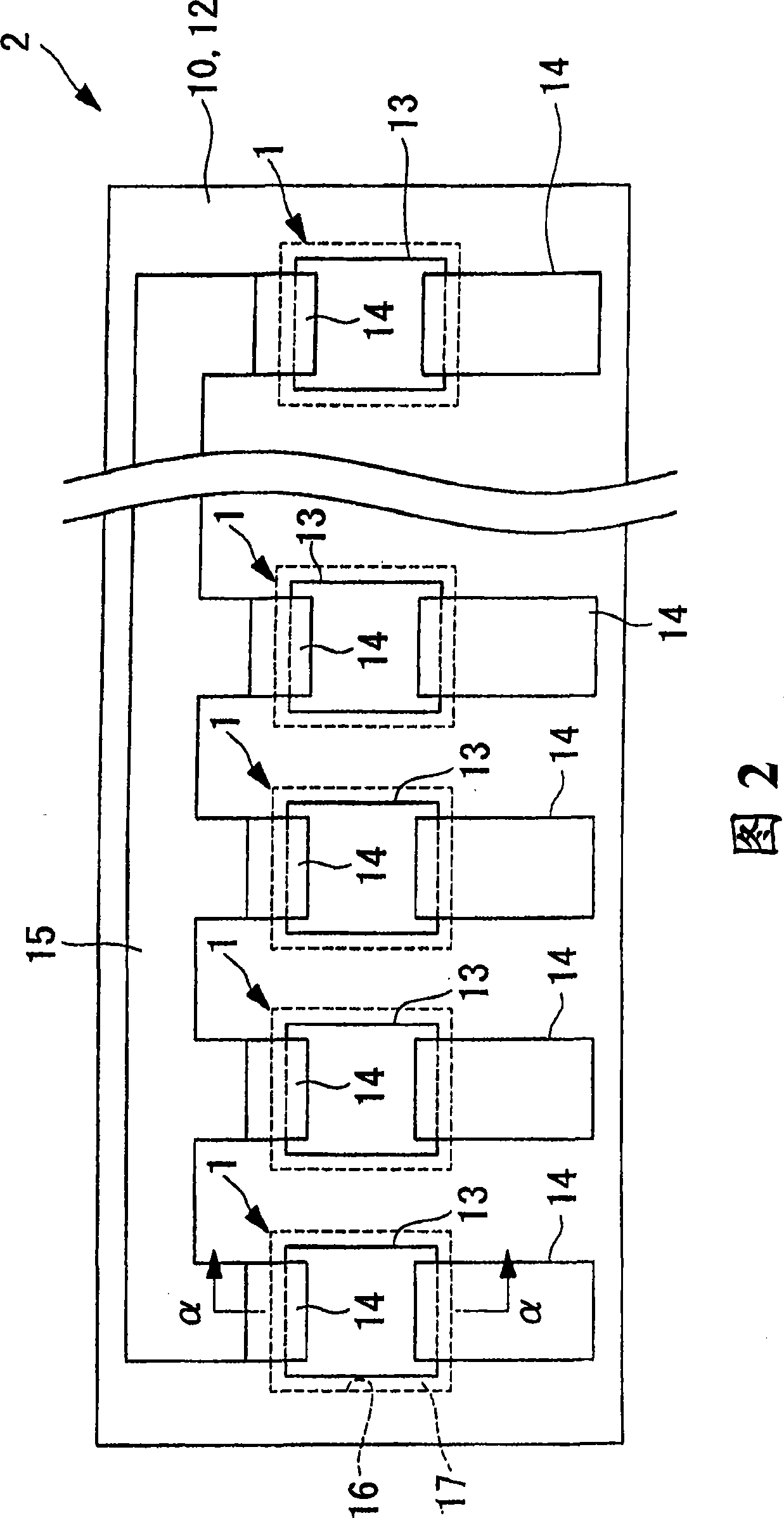
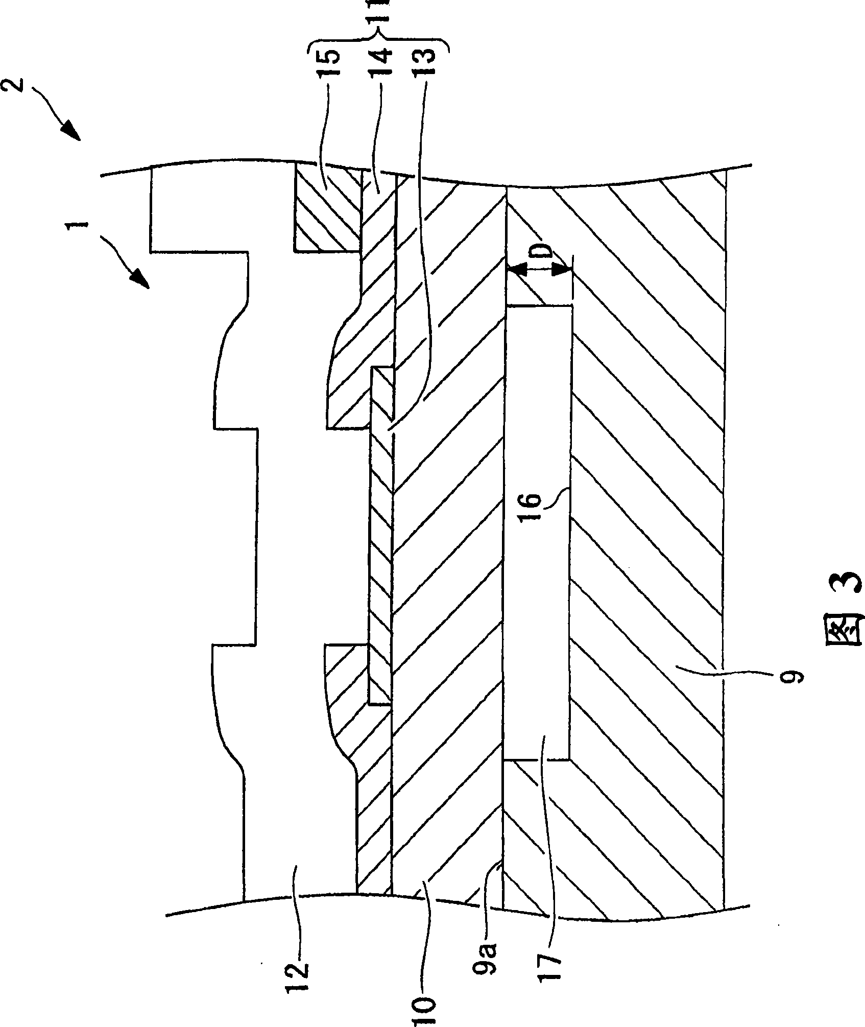
[0044] The thermal head 2 is formed in a flat plate shape as shown in the front view of FIG. 2, and includes a plurality of heating resistance ele...


PUM

PropertyMeasurementUnit
Roughnessaaaaaaaaaa
Depthaaaaaaaaaa

Abstract

The present invention relates to a heating resistor element and manufacture method thereof, and a thermal head and a printer. Provided is a heating resistor element (1), including: an insulating substrate (9); a heat accumulating layer (10) bonded to a surface of the insulating substrate (9); and a heating resistor (11) provided on the heat accumulating layer (10), in which: on at least one of bonded surfaces (9a) between the insulating substrate (9) and the heat accumulating layer (10), at least one of the insulating substrate (9) and the heat accumulating layer (10) is provided with a concave portion (16) in a region opposed to the heating resistor (11) to form a hollow portion (17); an inner surface arranged in the hollow portion of the heat accumulating layer is formed glossily, and the inner surface being processed to have surface roughness (Ra) of 0.2 mum or more. Accordingly, heat accumulation in a gas of the hollow portion (17) can be suppressed to improve printing quality.

Description

technical field [0001] The invention relates to a heating resistance element, a manufacturing method thereof, a thermal head and a printer. Background technique [0002] Generally, in a heating resistor provided in a thermal head of a printer, in order to improve the heating efficiency of the heating resistor and reduce power consumption, a hollow portion is formed in a region opposite to the heating resistor, and the hollow portion is used as a A thermal insulation layer of low thermal conductivity, thereby controlling the heat flow from the heating resistor to the side of the isolated substrate (see eg JP 2007-83532A). [0003] As a method of forming the hollow portion, a method is employed in which a silicon substrate is subjected to etching or laser processing, and a recessed portion (having a depth of 1 μm or more and 100 μm or less) is formed to Anodic bonding is performed to bond thereto a thin plate glass (having a thickness of 10 μm to 100 μm) serving as a heat gat...

Claims


Application Information

Patent Timeline
IPC IPC(8): B41J2/335
Inventor 顷石圭太郎师冈利光东海林法宜佐藤义则三本木法光
Owner SEIKO INSTR INC
Why Eureka
Try Eureka