Roller transmission mechanism for drafting assembly of spinning frame

A drafting device and transmission mechanism technology, applied to spinning machines, drafting equipment, spinning machines with continuous winding, etc., can solve the problems of increasing material consumption, reducing slippery rate, increasing mechanical transmission load, etc., and achieve reduction Effects of material consumption, improvement of yarn quality, and reduction of frictional resistance

Inactive Publication Date: 2009-04-29
SHIJIAZHUANG CHANGSHAN BEIMING TECH CO LTD
View PDF0 Cites 3 Cited by
  • Summary
  • Abstract
  • Description
  • Claims
  • Application Information

AI Technical Summary

Problems solved by technology

The above-mentioned problems in the transmission mechanism composed of friction are as follows: 1. In order to obtain sufficient friction force, there must be sufficient pressure, but the increase in pressure will inevitably increase the mechanical transmission load, increase power consumption, and the parts are easy to wear and increase. 2. Due to the uncertainty of the friction transmission ratio, it often occurs that the movement speed of the upper and lower rubber rings is inconsistent due to insufficient friction, resulting in inflexible movement of the moving...

Method used


Image

  • Roller transmission mechanism for drafting assembly of spinning frame
  • Roller transmission mechanism for drafting assembly of spinning frame
  • Roller transmission mechanism for drafting assembly of spinning frame

Examples


Embodiment Construction

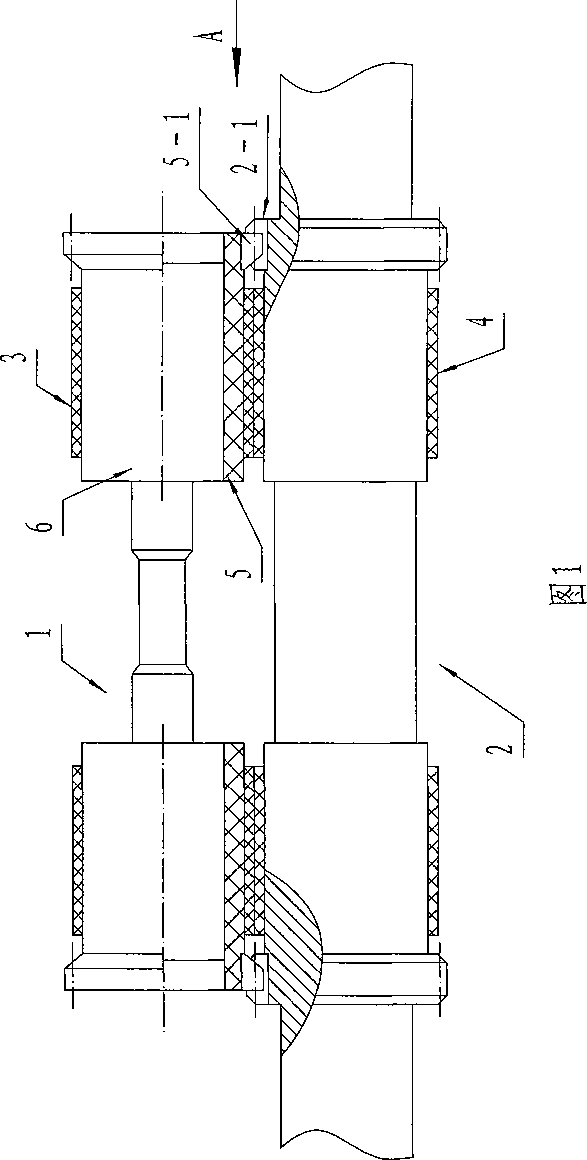
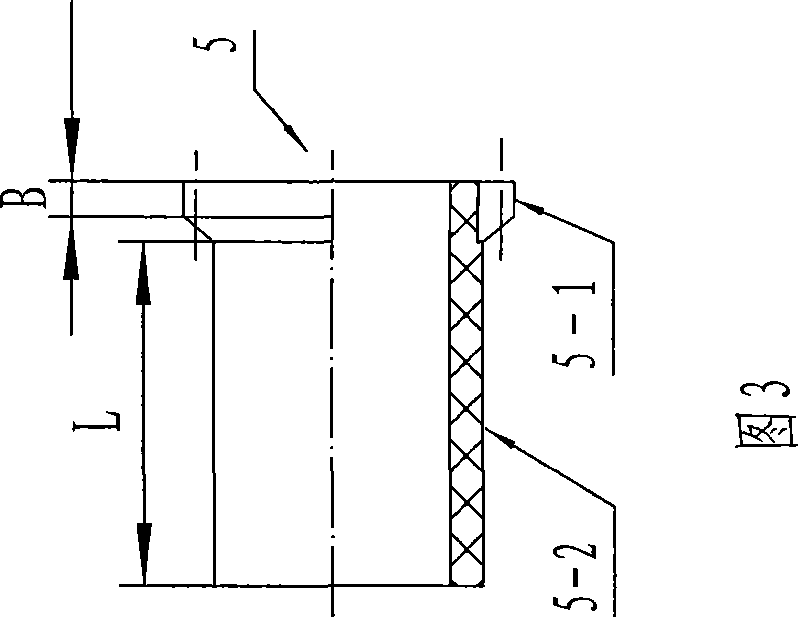
[0016] The invention improves the roller transmission mechanism of the drafting device aiming at the root cause of the slippery rate of the apron. Referring to Fig. 1 and Fig. 2, the composition of the present invention includes the lower middle roller 2 of the driving element, the upper middle roller 1 of the driven element, and the upper apron 3 and the lower apron 4 positioned on the upper and lower middle rollers. A pair of gears with the same number of teeth forms a transmission connection between the upper middle roller and the lower middle roller. Among them, the driving gear 2-1 with an integrated structure is cut out on the lower middle roller; the upper middle roller is composed of a rubber roller bearing 6 and a gear sleeve 5 with an interference fit with it. This structure is beneficial to the maintenance and replacement of the driven gear, and can improve The coefficient of friction between the gear sleeve and the upper rubber ring. Referring to Fig. 3, the gear ...


PUM

PropertyMeasurementUnit
Lengthaaaaaaaaaa
Wall thicknessaaaaaaaaaa
Tooth widthaaaaaaaaaa

Abstract

The invention relates to a roller transmission mechanism for a drafting system of a spinning machine, which is used for solving the problem that the slip of a rubber ring is high so as to influence the yarn forming quality. The technical proposal of the roller transmission mechanism is as follows: the roller transmission mechanism comprises an upper-middle roller and a lower-middle roller which are in transmission connection, an upper rubber ring arranged on the upper-middle roller and a lower rubber ring arranged on the lower-middle roller, wherein the lower-middle roller is a driving part, and the improved upper-middle roller and lower-middle roller are in transmission connection through a pair of gears with the same tooth number. The machine has the advantages as follows: 1. the roller transmission mechanism can ensure that the upper and lower rollers synchronously rotate, greatly reduce the slip between the upper rubber ring and the lower rubber ring, is favorable for feeding strands to a front roller jaw, improve the yarn forming quality, and reduce bunchy yarn; and 2. under the condition of ensuring enough gripping power to the strands, the cradle pressure and the power to drive the drafting system to work are properly reduced, thereby reducing energy consumption and abrasion of related parts, saving production cost and reducing material consumption.

Description

technical field [0001] The invention relates to a textile machine, in particular to a roller transmission mechanism for a spinning frame drafting device, which belongs to the technical field of textiles. Background technique [0002] The role of the textile spinning frame is to draft the roving strands to become thinner through the drafting device, and then form spun yarns through winding and twisting. The basic composition of the drafting device includes three pairs of rollers, wherein the two pairs of rollers located at the front and the rear are simple roller drafts consisting of upper top rollers and lower rollers, and the main drafting member located in the middle is composed of upper and middle rollers. , the upper pin and the upper apron surrounding the upper middle roller and the upper pin; the lower middle roller, the lower pin and the lower apron surrounding the lower middle roller and the lower pin form an elastic jaw, and thus generate a middle friction boundary ...

Claims


Application Information

Patent Timeline
IPC IPC(8): D01H1/22D01H3/14D01H5/74
Inventor 赵瑞忠侯成才聂中印
Owner SHIJIAZHUANG CHANGSHAN BEIMING TECH CO LTD
Why Eureka
Try Eureka