Air conditioner

An air conditioner and air-conditioning technology, which is applied in air-conditioning systems, space heating and ventilation, household heating, etc., can solve the problems of equipment cost, heat source device operation cost and equipment cost, long piping distance, etc. Less loss, less running cost, less equipment cost

Active Publication Date: 2010-09-01
KIMURA KOHKI CO LTD
View PDF3 Cites 0 Cited by
  • Summary
  • Abstract
  • Description
  • Claims
  • Application Information

AI Technical Summary

Problems solved by technology

This 4-pipe heat source water line requires equipment costs due to long piping distances, and also has the problem of costing the operating cost of the heat source device and the equipment cost because it needs to produce cold water and hot water at the same time.

Method used


Image

  • Air conditioner
  • Air conditioner
  • Air conditioner

Examples


Embodiment approach 1

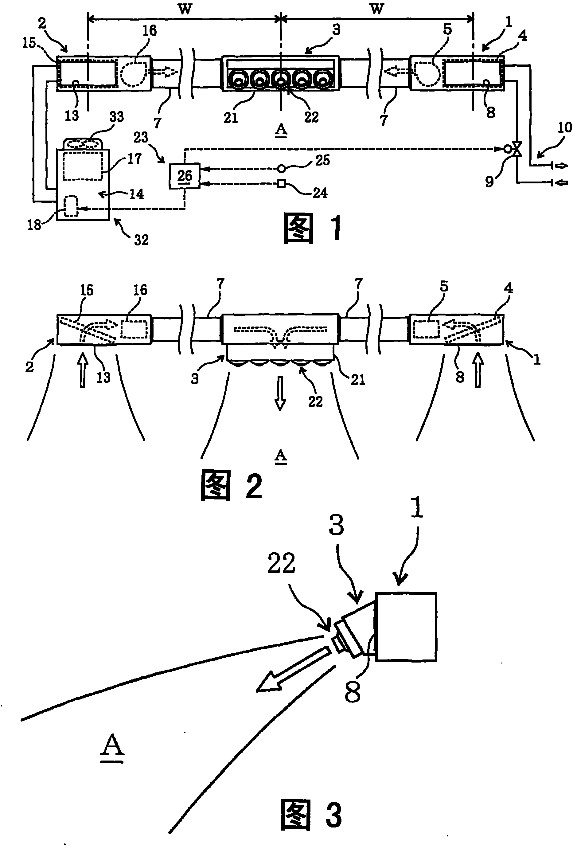
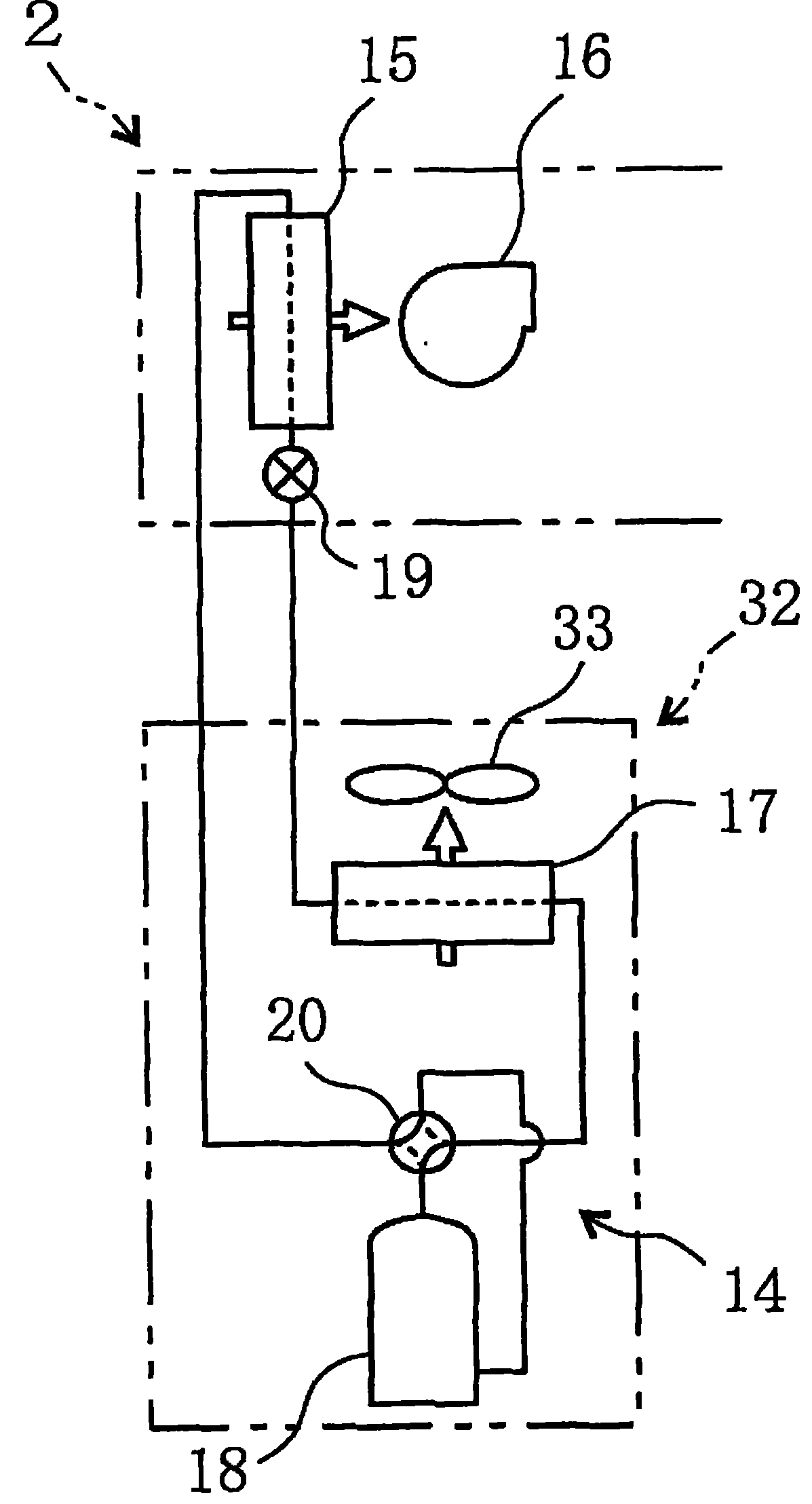
[0050] figure 1 , figure 2 and image 3 A front view, a top view, and a side view schematically showing the structure of the air conditioner according to Embodiment 1 of the present invention, Figure 4 It is an explanatory diagram schematically showing the structure of the heat pump included in the air conditioner.

[0051] The air conditioner is a device for air-conditioning by circulating air in an air-conditioned area A in a large indoor space, and is installed on a wall, a beam, or a ceiling. This air conditioner includes a hot water side unit 1 , a heat pump side unit 2 , a blower unit 3 , an air heat source unit 32 , and a control unit 23 . in, figure 1 The dashed hollow arrows indicate the wind direction of the air for air supply, and the solid solid arrows indicate the direction of water flow in the heat source water circuit 10 . figure 2 and image 3 The shown solid and dashed hollow arrows indicate the wind direction of the supply air. Figure 4 Among the s...

Embodiment approach 2

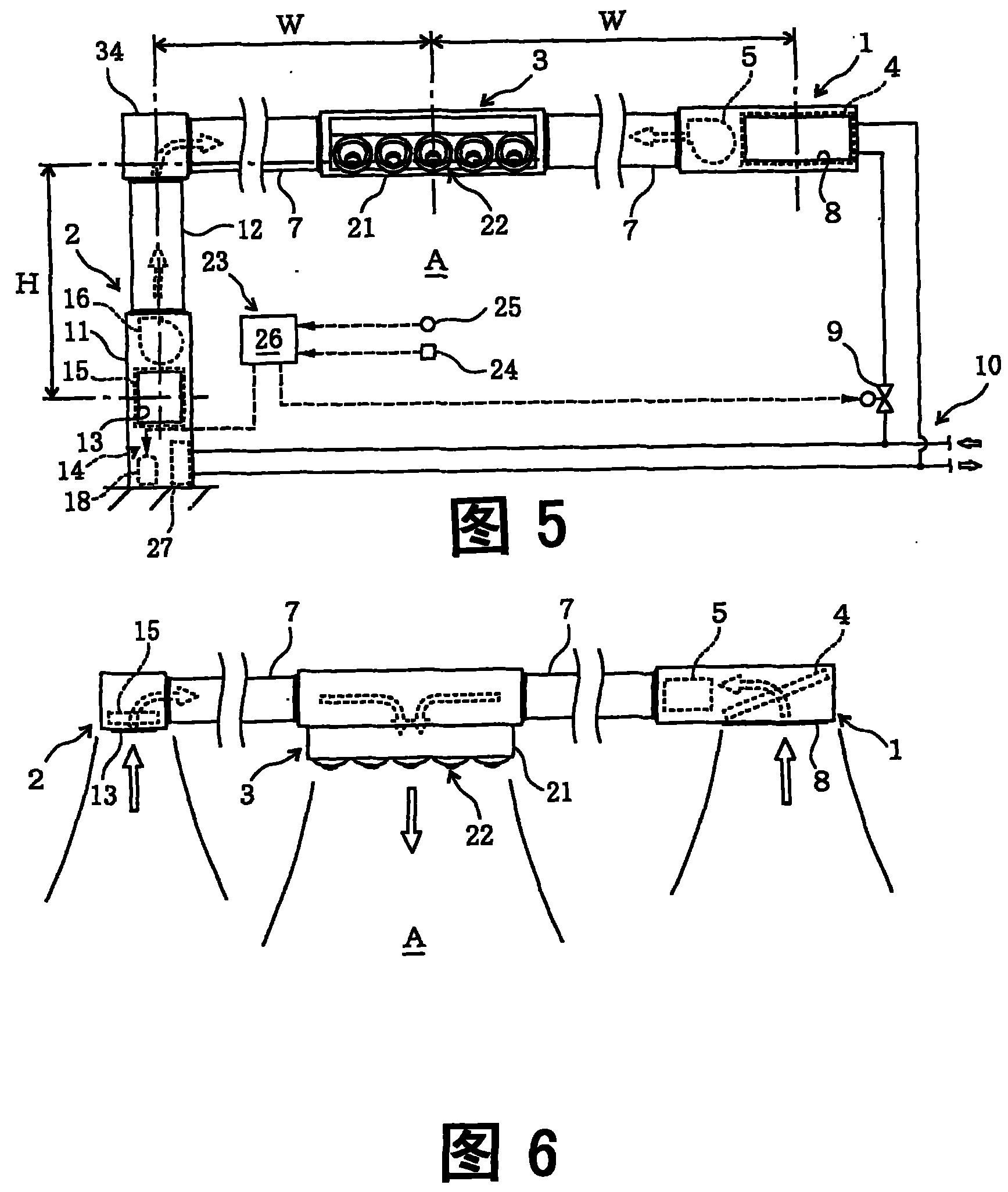
[0067] Figure 5 , Figure 6 and Figure 7 A front view, a top view, and a side view schematically showing the structure of an air conditioner according to Embodiment 2 of the present invention, Figure 8 It is an explanatory diagram schematically showing the structure of the heat pump included in this air conditioner. in, Figure 8 Among the solid line hollow arrows shown, the hollow arrow near the water heat exchanger 27 for the heat source indicates the direction of water flow.

[0068] The configuration of the air conditioner of the present embodiment is substantially the same as that of the first embodiment, but includes a heat pump 14 for a compressed water heat source instead of the heat pump 14 for a compressed air heat source included in the air conditioner.

[0069] Furthermore, the heat pump side unit 2 is not horizontally long in the left and right direction but vertically long in the vertical direction, and a heat pump side suction port 13 for sucking in air i...

Embodiment approach 3

[0075] Figure 9 It is a front view schematically showing the configuration of the air conditioner according to Embodiment 3 of the present invention.

[0076] The structure of the air conditioner of the present embodiment is substantially the same as the structure of the air conditioner of Embodiment 2, but the heat source of the heat pump 14 is used to connect the pipes in series and make the cold and hot water with low energy available after circulating in the hot and cold water coil 4 A structure that circulates in the water heat exchanger 27, and a part or all of the low-energy cold and hot water that bypasses the cold and hot water coil 4 is set to control the flow of the cold and hot water that circulates in the heat source water heat exchanger 27 The flow control mechanism 29.

[0077] In this embodiment, the flow control mechanism 29 is composed of a bypass channel 30 bypassing the heat source water inlet and outlet of the cold and hot water coil 4 and a flow regulat...


PUM


Abstract

The invention provides an air conditioner which can save energy and lower equipment cost and operation cost. In order to condition air by inner circulation of an air-conditioned area (A) in a large area, the conditioner comprises: a cold-heat water component (1) provided with a cold-heat water coil using low-usable energy cold-heat water and air sucked from the air-conditioned area to exchange heat; a heat pump side component (2) provided with an air-supplying air heat exchanger using a circulation heat medium with usable energy thereof higher than that of the low-usable energy cold-heat water and air sucked from the air-conditioned area to exchange heat; a blowing component (3) blowing the air passing through the cold-heat water coil and the air passing through the air-supplying air heatexchanger to the air-conditioned area; a heat pump (14) for a compressed air heat source, provided with the air-supplying air heat exchanger, and circulating the circulation heat medium; and a control unit (23) controlling flux of the cold-heat water flowing through the cold-heat water coil and the compression volume of a compressor of the heat pump.

Description

technical field [0001] The present invention relates to an air conditioner that circulates air in an area to be conditioned to condition the air. Background technique [0002] In the past, air conditioning (hereinafter referred to as "air conditioning") in large spaces such as factories, large stores, supermarkets, and gymnasiums was carried out with hot and cold water central air conditioners such as air conditioning equipment to regulate the entire large space. The hot and cold water central air conditioner adopts such a structure: through the cold and hot water coils in which cold water or hot water (hereinafter referred to as "hot and cold water") flows as heat source water, the heat source water and the The air sucked into the area (return air) is heat-exchanged and supplied to the area to be conditioned, and the air is circulated in the area to be conditioned to perform air conditioning (hereinafter referred to as cycle air conditioning) (see Patent Documents 1 to 3). ...

Claims


Application Information

Patent Timeline
Patent Type & Authority Patents(China)
IPC IPC(8): F24F3/06
Inventor 木村惠一森田满津雄
Owner KIMURA KOHKI CO LTD
Why Eureka
Try Eureka