Bidirectional composite force loading test device for masonry test piece

A technology for loading test devices and test pieces, which is applied in the direction of measuring devices, instruments, scientific instruments, etc., can solve the problems of less loading devices, difficult test, inconvenient installation of instruments, etc., to meet loading requirements, convenient loading control, and accurate data reliable effect

Inactive Publication Date: 2009-04-29
TONGJI UNIV
View PDF0 Cites 25 Cited by
  • Summary
  • Abstract
  • Description
  • Claims
  • Application Information

AI Technical Summary

Problems solved by technology

At present, most of the two-way composite force loading test devices for masonry use two-way jacks for loading. Therefore, the jack in one direction needs to be adjusted at any time to ensure the constant lateral loading value. The operation is complicated and it is easy to cause danger when the specimen is damaged.
Since the jack needs to be fixed in two directions, the loading device occupies a large area and the installation of the

Method used


Image

  • Bidirectional composite force loading test device for masonry test piece
  • Bidirectional composite force loading test device for masonry test piece
  • Bidirectional composite force loading test device for masonry test piece

Examples


Embodiment 1

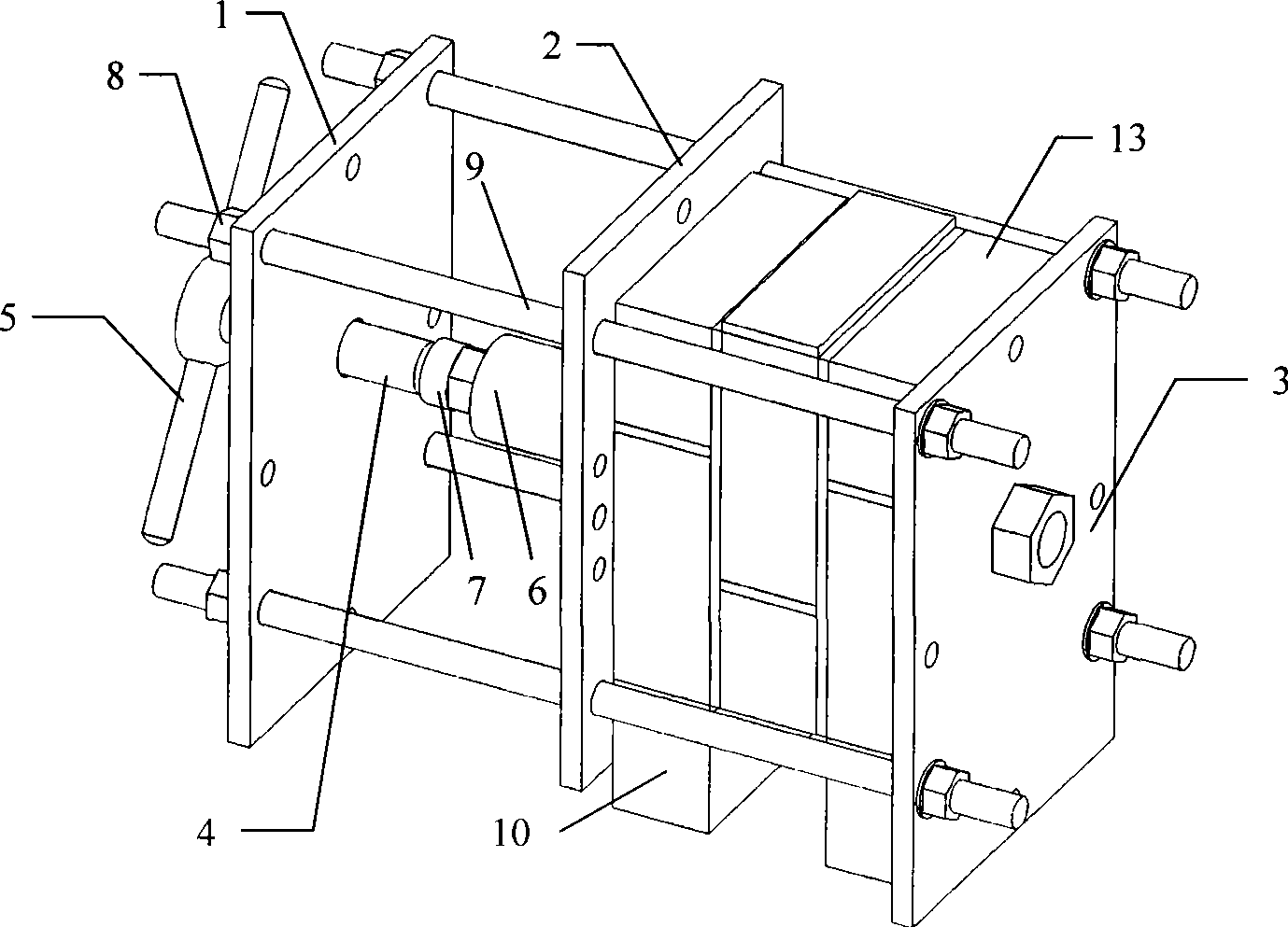
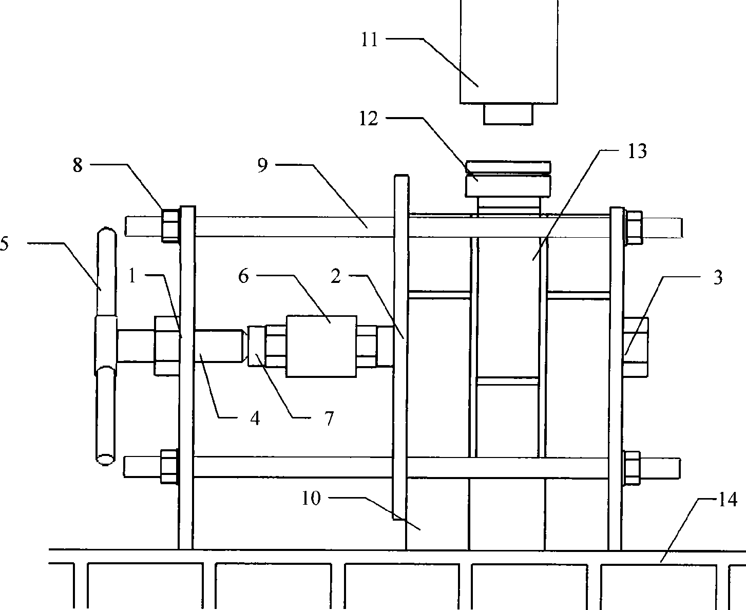
[0030] When the present invention is used as a compression-shear composite force loading device for a masonry double-shear test piece (see for details figure 1 , image 3 and Figure 4 ), the reaction frame is assembled by three steel plates and four screw rods 9, and the four jiaos of the steel plates have circular holes, and the three steel plates are connected by the screw rods through the circular holes. Left and right two steel plates are fixed its relative distance by outer nut 8, and middle steel plate 2 can slide arbitrarily therebetween. Wherein the middle of left steel plate 1 has circular hole and is welded with big nut, and pressure screw rod 4 surface has supporting screw thread and passes through in big nut, and the middle of right steel plate 3 is welded with the nut that is used for balancing bending moment. One end of the pressure screw 4 is torqued by a wrench 5 to achieve manual pressure, and the other end is processed into a hemispherical surface to withs...

Embodiment 2

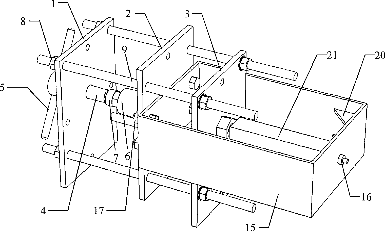
[0039] When the present invention is used as the pull-shear composite force loading device of mortar test block (see for details figure 2 , Figure 5 and Image 6 ), on the basis of the pressure-shear device, a mouth-shaped steel frame 15 is added, on which stiffeners 20 are welded. Fix the square-shaped steel frame 15 on the middle steel plate 2 with bolts 17, which will convert the pressure generated by the pressing screw 4 into the tensile force on the test piece. A small hole is respectively opened in the middle of the right steel plate 3 and the middle of the right side of the mouth-shaped steel frame 15, and the pre-embedded steel bars at both ends of the mortar test block 21 pass through respectively, and are fixed with nuts 16 (threads are processed at the ends of the steel bars in advance) .

[0040] In order to carry out the tensile-shear composite stress loading test of mortar test block and other specimens, the present invention can complete the loading task ac...


PUM


Abstract

The invention relates to a bidirectional composite stress loading test device for a test piece of a brick body and belongs to the field of civil engineering. The device mainly comprises an adjustable reaction frame, a pressurization screw stem and a mouth-shaped frame; the steel reaction frame which can adjust distance and the pressurization screw stem with a force transducer are utilized to realize the loading of transverse pressure or tensile force of the test piece of the brick body; and the largest loading value of the pressurization screw stem can reach 150 kN. The steel reaction frame consists of a steel plate and a screw stem; and the relative distance of the steel plate of the reaction frame can be flexibly adjusted so as to meet the requirement of the test pieces with different specifications. The vertical direction of the test piece is matched with the prior hydraulic jack to realize a full-process bidirectional loading test on the test piece of the brick body. The loading device has a simple structure, convenient disassembly and assembly and small occupied area, can be repeatedly used, can move, is convenient to load and control, has accurate and reliable tested data and can fully meet the loading requirement of the bidirectional composite stress loading test on the test piece of the brick body.

Description

technical field [0001] The invention belongs to the field of civil engineering, and relates to a loading test device, in particular to a two-way composite force loading test device for masonry specimens, which provides a simple and practical loading test device for studying the two-way force performance of masonry or other materials. tool. Background technique [0002] In the building structure, there are very few components that are only subjected to one kind of load. Under the composite stress state, the materials in the components are in a complex stress state. Therefore, it is necessary to determine the mechanical properties and damage of components and materials under the composite stress. Form is one of the key contents of structural engineering research. As an ancient and new material, masonry is widely used in various structural fields. With the continuous emergence of various new masonry materials, the research on the properties of masonry materials under composit...

Claims


Application Information

Patent Timeline
IPC IPC(8): G01N3/00
Inventor 顾祥林马俊元李翔王卓琳陈贡联
Owner TONGJI UNIV
Why Eureka
Try Eureka