Cooling system for testing longevity of hybrid vehicle controller

A technology for vehicle controllers and hybrid electric vehicles, applied in general control systems, engine cooling, control/regulation systems, etc., can solve problems such as controller and motor burnout, failure, and unstable operating temperature of hybrid electric motors. Achieve the effect of low cost and simple structure

Inactive Publication Date: 2009-04-29
CHERY AUTOMOBILE CO LTD
View PDF0 Cites 14 Cited by
  • Summary
  • Abstract
  • Description
  • Claims
  • Application Information

AI Technical Summary

Problems solved by technology

In this way, the operating temperature of the hybrid vehicle controller and the hybrid motor are unstable. Once their actual operating temperature exceeds the normal temperature range, the controller and the motor may be burned, and the entire hybrid vehicle may be damaged. The damage of the controller life test system and the failure of the test, so in the life test of the hybrid vehicle controller must have a set of cooling system to ensure that the controller, motor and other key components work within the normal temperature range

Method used


Image

  • Cooling system for testing longevity of hybrid vehicle controller
  • Cooling system for testing longevity of hybrid vehicle controller

Examples


Embodiment 1

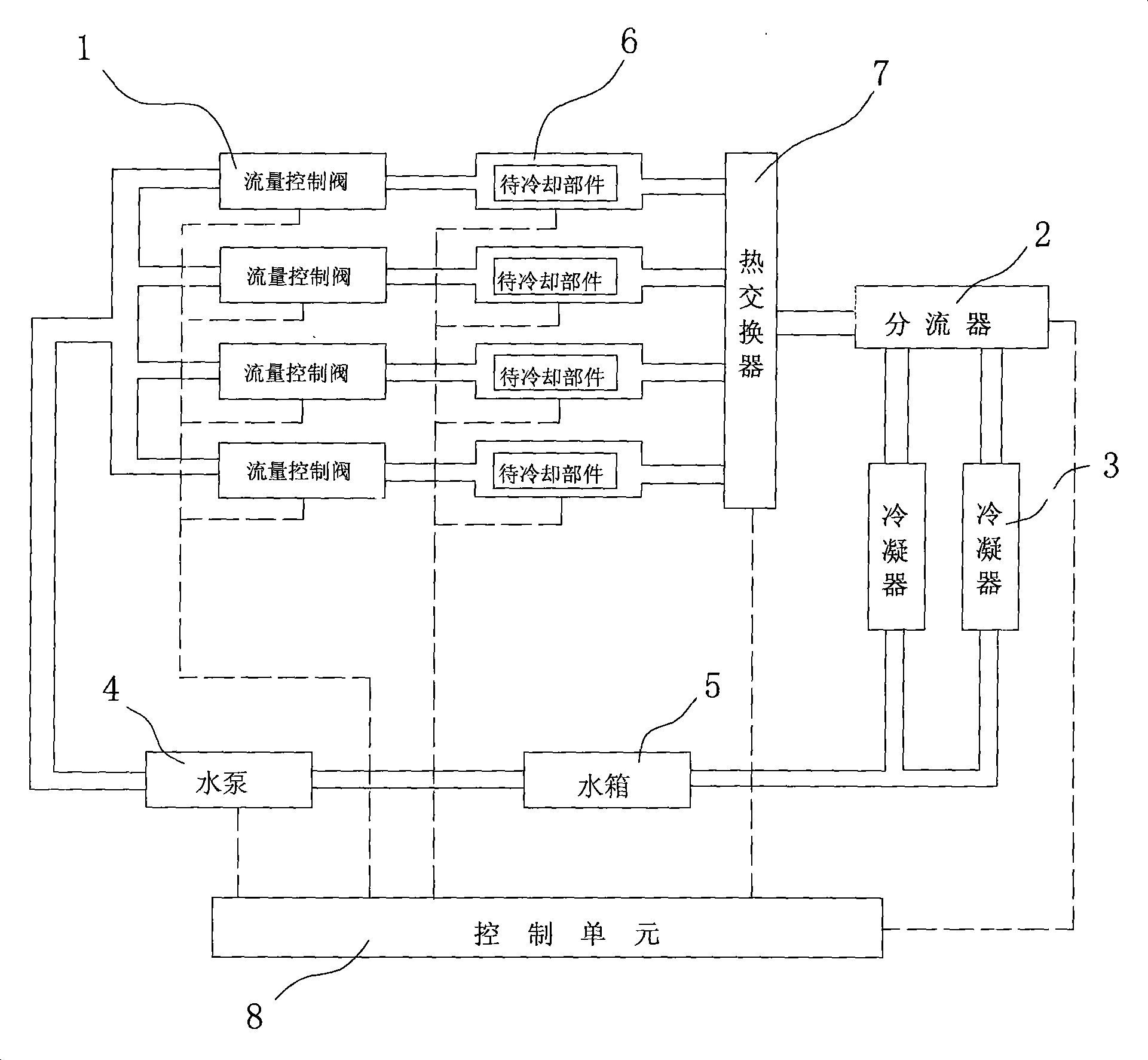
[0019] Such as figure 1 As shown, the cooling system used for the life test of the hybrid vehicle controller in this embodiment includes a control unit 8, four flow control valves 1, a water pump 4, a flow divider 2, two condensers 3, a water tank 5 and four A cooling bench 6 provided with a temperature sensor, and a communication cable is connected between the control unit 8 and the temperature sensor, the water pump 4, the flow control valve 1 and the shunt 2 of the cooling bench 6 (the communication cable is connected with the dotted line in the figure). express).

[0020] The water pump 4 is connected to the water tank 5 by pipelines, and the cooling water pumped from the water tank 5 by the water pump 4 is distributed to a plurality of flow control valves 1, and each flow control valve 1 is connected to a hollow cooling stand 6 for placing components to be cooled. connected, the cooling water flows from the flow control valve 1 to the corresponding cooling stand 6, and c...

Embodiment 2

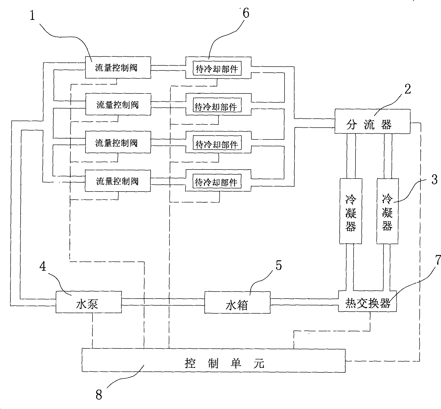
[0023] Such as figure 2 As shown, different from the above-mentioned embodiment 1, the heat exchanger 7 of this embodiment is arranged at the position between the condenser 3 and the water tank 5, and the cooling water flowing out of the cooling platform 6 passes through the condenser 3 First pass through the heat exchanger 7, and then return to the water tank 5, which can also achieve the purpose of accelerating the heat exchange of cooling water, so as to adapt to the large difference in the length of the cooling water circulation path where each condenser 3 is located in some vehicle test systems. Case.


PUM


Abstract

The invention aims at providing a cooling system for the lift test of a whole vehicle controller of a hybrid engine vehicle, which comprises a control unit, a flow metering valve, a water pump, a flow divider, a condenser, a water tank and a cooling stage provided with temperature sensors, wherein, the control unit receives temperature signals transmitted by the temperature sensors of the cooling stage and transmits control signals to the water pump, the flow metering valve and the flow divider to control the work of the water pump, the flow metering valve and the flow divider, cooling water pumped from the water tank by the water pump is divided into a plurality of flow metering valve and the cooling stage communicated with the flow metering valves, cooling water passing through the cooling stage is combined to the flow divider, and then the water passes through one or more condensers to come back to the water tank. The cooling system of the invention adopts a water circulation cooling method, the control unit has reliable temperature control methods for each cooling stage, and all cooling parts such as the whole vehicle controller, motors, and the like can be ensured to work in temperature ranges required for respective tests.

Description

technical field [0001] The invention relates to a test system of a hybrid electric vehicle, in particular to a cooling system used in a life test system of a controller of a hybrid electric vehicle. Background technique [0002] With the energy crisis and the strengthening of people's awareness of environmental protection, energy-saving, environmentally friendly, and efficient new energy vehicles have become a new trend in the development of the automotive industry. Among them, hybrid electric vehicles (Hybrid Electric Vehicle, abbreviated as HEV) have the advantages of low emissions of electric vehicles Compared with the high specific energy advantages of internal combustion engine vehicles, it has attracted more and more attention. [0003] The hybrid vehicle described in this article refers to a moderately hybrid (ISG, integrated starter generator) vehicle, in addition to the configuration of a conventional car, it also includes a hybrid vehicle controller installed betwe...

Claims


Application Information

Patent Timeline
IPC IPC(8): G05D23/20G05D23/01G05D23/185G05B23/00
CPCF01P7/165F01P9/02F01P2050/24
Inventor 王冬
Owner CHERY AUTOMOBILE CO LTD
Why Eureka
Try Eureka