Precision roll turning lathe

A roll lathe, precision technology, applied in the field of precision roll lathe, can solve the problem of reduced machining accuracy, and achieve the effect of shortening time, high efficiency, and high precision

Active Publication Date: 2009-05-06
TOSHIBA MASCH CO LTD
View PDF3 Cites 9 Cited by
  • Summary
  • Abstract
  • Description
  • Claims
  • Application Information

AI Technical Summary

Problems solved by technology

This vibration will greatly reduce the machining accuracy

Method used


Image

  • Precision roll turning lathe
  • Precision roll turning lathe
  • Precision roll turning lathe

Examples


no. 1 example

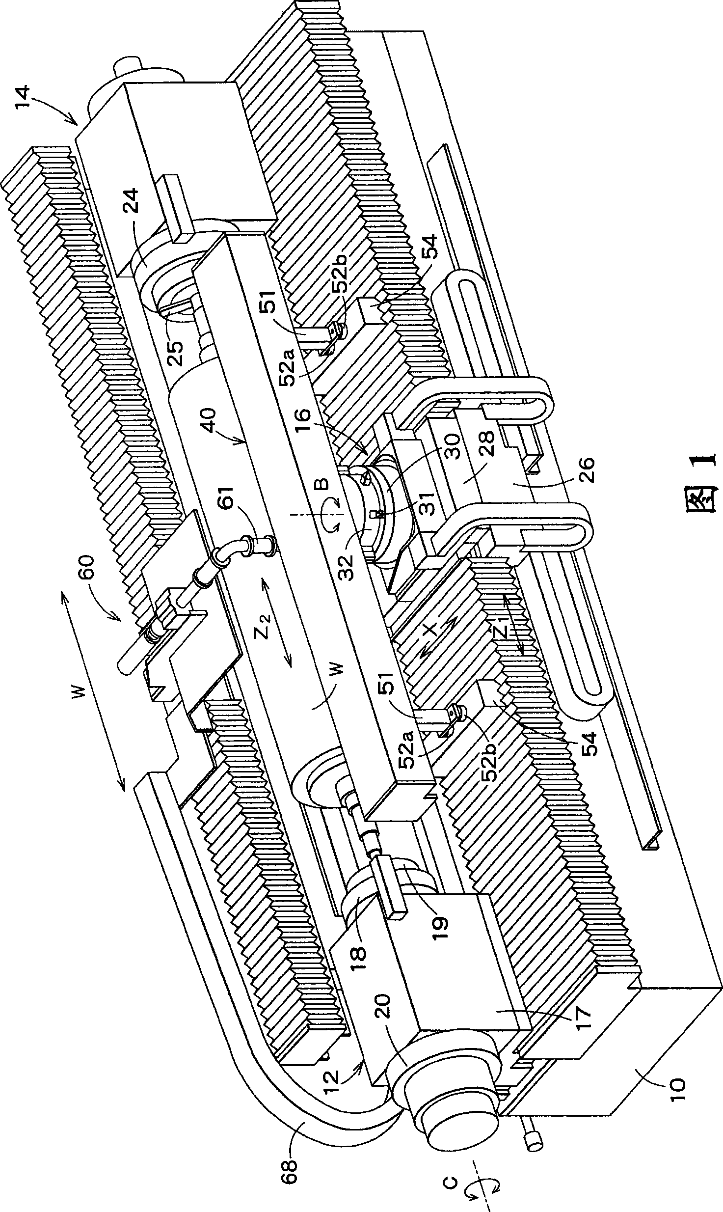
[0029] 1 is a front perspective view of a precision roll lathe according to a first embodiment of the present invention, and FIG. 2 is a rear perspective view of the precision roll lathe without a roll installed.

[0030] In Fig. 1 and Fig. 2, numeral 10 denotes a bed. A headstock 12 , a tailstock 14 and a support 16 are installed on the bed 10 . A roll W as a workpiece is rotatably supported by the headstock 12 and the tailstock 14 .

[0031] The head box 12 is located at one end of the bed 10 in the longitudinal direction. The headstock 12 includes a box body 17 , a main shaft 18 , a chuck 19 fixed on the front end of the main shaft 18 and a servo motor 20 for driving the main shaft 18 . The main shaft 18 is supported by a hydrostatic oil bearing (not shown) provided in the case 17 . The chuck 19 holds the spindle of the roll W, and transmits the rotation of the spindle 18 to the roll W. As shown in FIG.

[0032] In the headstock 12 , the servo motor 20 for driving the m...

no. 2 example

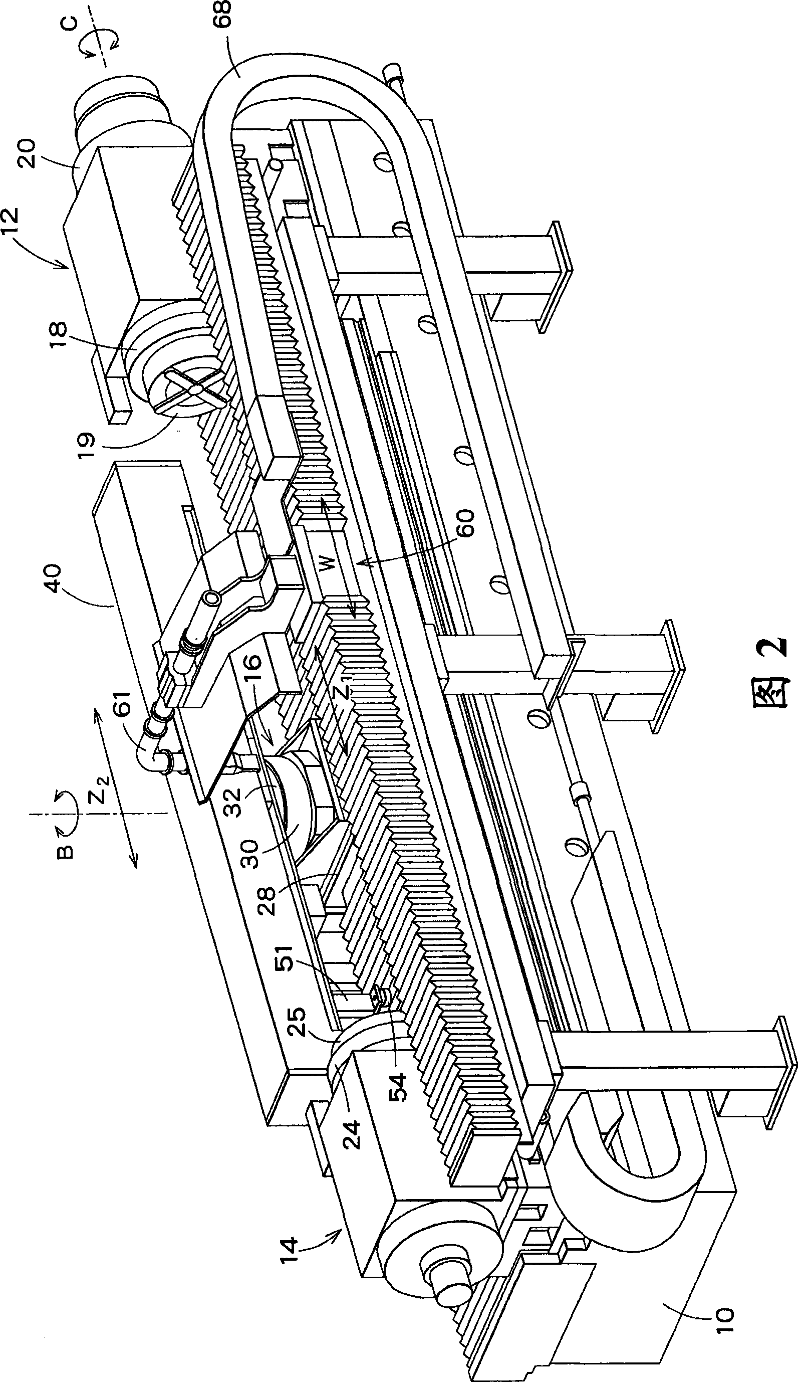
[0067] Now, a precision roll lathe according to a second embodiment of the present invention will be described with reference to FIG. 7 .

[0068] The roll lathe of this embodiment is characterized in that a chip suction device 60 shown in FIG. 7 is provided. As shown in FIG. 7 , the chip suction device 60 includes a moving table 61 and a support arm 62 . The moving table 61 moves on the bed 10 in a direction parallel to the moving direction of the slider 41 . A ball screw is used as a driving mechanism of the moving table 61, and a W-axis is used as a control axis of the driving mechanism.

[0069] The support arm 62 is fixed on the moving table 61 , and the support arm 62 extends toward the roller W. As shown in FIG. The suction duct 63 is supported by a support arm 62 . A joint 64 is mounted on the downwardly bent end of the suction duct 63 , and a suction nozzle 65 is connected to the suction duct 63 via the joint 64 . The tip of the suction nozzle 65 is located near t...


PUM


Abstract

There is provided a precision roll turning lathe which can perform machining of fine grooves at a dramatically higher speed as compared to conventional roll turning lathes, thus significantly shortening time taken for machining one groove. The precision roll turning lathe includes: a bed; a headstock, mounted on the bed, having a main spindle for rotating a roll as a workpiece while holding one end of the roll by means of a chuck; a tail stock, mounted on the bed and disposed opposite the headstock, for rotatably supporting the other end of the roll; a carriage including a saddle mounted on the bed movably in the longitudinal direction of the roll, and a table mounted on the saddle movably in a direction perpendicular to the longitudinal direction of the roll; and an air slide apparatus, mounted on the table, including a guide rail extending parallel to the roll in the longitudinal direction, an air slider having a diamond tool, capable of traveling in a floating state on the guide rail, and a linear motor for driving the air slider.

Description

technical field [0001] The present invention relates to a precision roll lathe, and more particularly to a precision roll lathe used in the processing of rolling dies for extrusion molding of optical products such as lens sheets. Background technique [0002] A roll lathe is a machine tool used to process rolls. A roll lathe is a lathe in which a tool holder attached such as a diamond tool is mounted on a stand, and the roll is rotated by a head box and the stand is fed in the lateral direction (X-axis direction) of the roll, thereby basically using A ring groove is machined on the roller. When machining the axial groove on the roller, when the roller is indexed by the headstock (C-axis), the bracket is fed along the longitudinal direction of the roller (Z-axis direction), thereby machining the axial groove. [0003] With the advancement of mechanical control technology in recent years, ultra-precision machining using roll lathes has been realized. At present, roll lathes...

Claims


Application Information

Patent Timeline
Patent Type & Authority Applications(China)
IPC IPC(8): B23B5/08B23B25/00B23Q1/38
Inventor 秋山贵信
Owner TOSHIBA MASCH CO LTD
Why Eureka
Try Eureka