Permanent magnet type dual electric power conversion switch
A technology of dual power conversion and dual power switching, which is applied to electric switches, high-voltage/high-current switches, power devices inside switches, etc., which can solve the problems of high cost, high processing precision, and long operating time, and achieve a large footprint Effects of small size, high reliability, and few sources of failure
- Summary
- Abstract
- Description
- Claims
- Application Information
AI Technical Summary
Problems solved by technology
Method used
Image

Examples
Embodiment 1
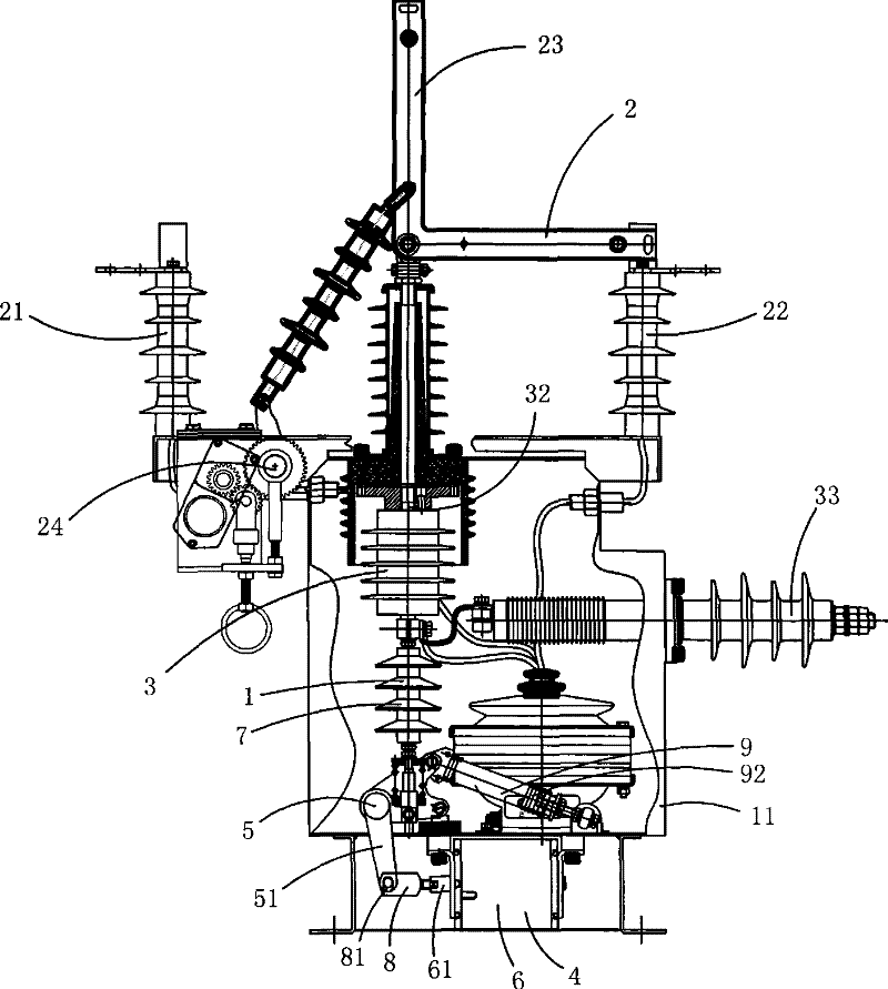
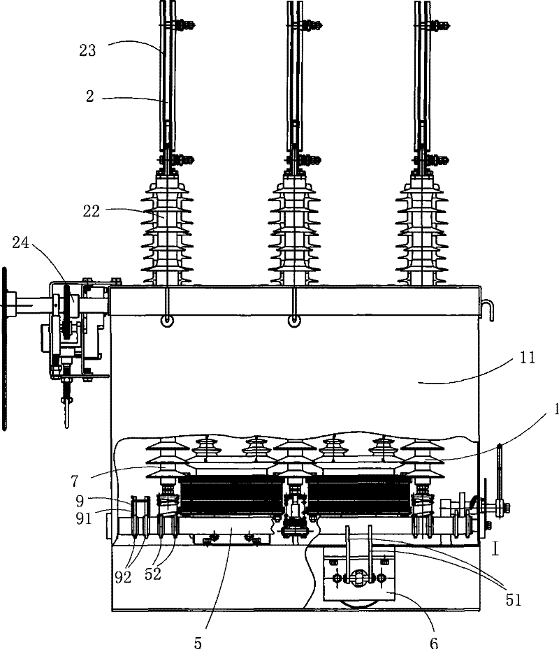
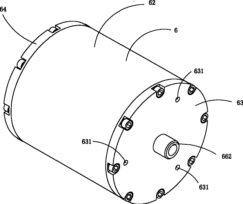
[0037] Figure 1 to Figure 7 The first specific embodiment of the present invention is shown, in which, figure 1 Is a schematic diagram of the first structure of the present invention; figure 2 Yes figure 1 The shown schematic diagram of the structure of the permanent magnet type dual power switch when viewed from another angle; image 3 Yes figure 1 A schematic diagram of a three-dimensional structure of the permanent magnet drive mechanism in the permanent magnet type dual power transfer switch shown; Figure 4 Yes image 3 The structure diagram of the permanent magnet drive mechanism shown when viewed from the direction of the front cover; Figure 5 Yes Figure 4 Sectional view along the line A-A; Image 6 Yes image 3 A schematic diagram of a three-dimensional structure of the permanent magnet drive mechanism after the front cover is removed; Figure 7 Yes image 3 A schematic diagram showing a half-section structure of the permanent magnet drive mechanism after the permanent ...
Embodiment 2
[0049] Figure 8 It is a half-sectional structural schematic diagram of the permanent magnet drive mechanism used in the second structure of the present invention after the permanent magnet is removed, showing the second embodiment of the present invention.
[0050] This embodiment is basically the same as embodiment 1, the difference is: see Figure 8 , The arrangement of the permanent magnet is different. In this embodiment, the inner wall of the housing 62 is provided with an annular groove 100 for limiting the permanent magnet 67, and the permanent magnet 67 is disposed in the groove 100. This structure enables the adjusting bolt to limit the yoke ring and at the same time limit the permanent magnet to avoid loosening and displacement due to vibration.
Embodiment 3
[0052] Picture 9 It is a half-sectional structural diagram of the permanent magnet drive mechanism used in the third structure of the present invention after the permanent magnet is removed, and shows the third embodiment of the present invention.
[0053] This embodiment is basically the same as embodiment 1, the difference is: see Picture 9 , The arrangement of the permanent magnet is different. In this embodiment, the outer wall of the yoke ring 68 is provided with an annular groove 100 for limiting the permanent magnet 67, and the permanent magnet 67 is arranged in the groove 100. This structure enables the adjusting bolt to limit the yoke ring and at the same time limit the permanent magnet to avoid loosening and displacement due to vibration.
PUM
 Abstract
Description
Claims
Application Information
 - R&D
- Intellectual Property
- Life Sciences
- Materials
- Tech Scout
- Unparalleled Data Quality
- Higher Quality Content
- 60% Fewer Hallucinations
Browse by: Latest US Patents, China's latest patents, Technical Efficacy Thesaurus, Application Domain, Technology Topic, Popular Technical Reports.
© 2025 PatSnap. All rights reserved.Legal|Privacy policy|Modern Slavery Act Transparency Statement|Sitemap|About US| Contact US: help@patsnap.com