

LED instantaneous light flux test method and apparatus in PWM activation technology
A test method and luminous flux technology, applied in the field of measurement, can solve the problems of inconvenient research work, inability to meet the needs of LED instantaneous luminous flux measurement, lack of test methods and test tools, etc., to achieve the effect of dynamic measurement
- Summary
- Abstract
- Description
- Claims
- Application Information
AI Technical Summary
Problems solved by technology
Method used
Image

Examples
Embodiment
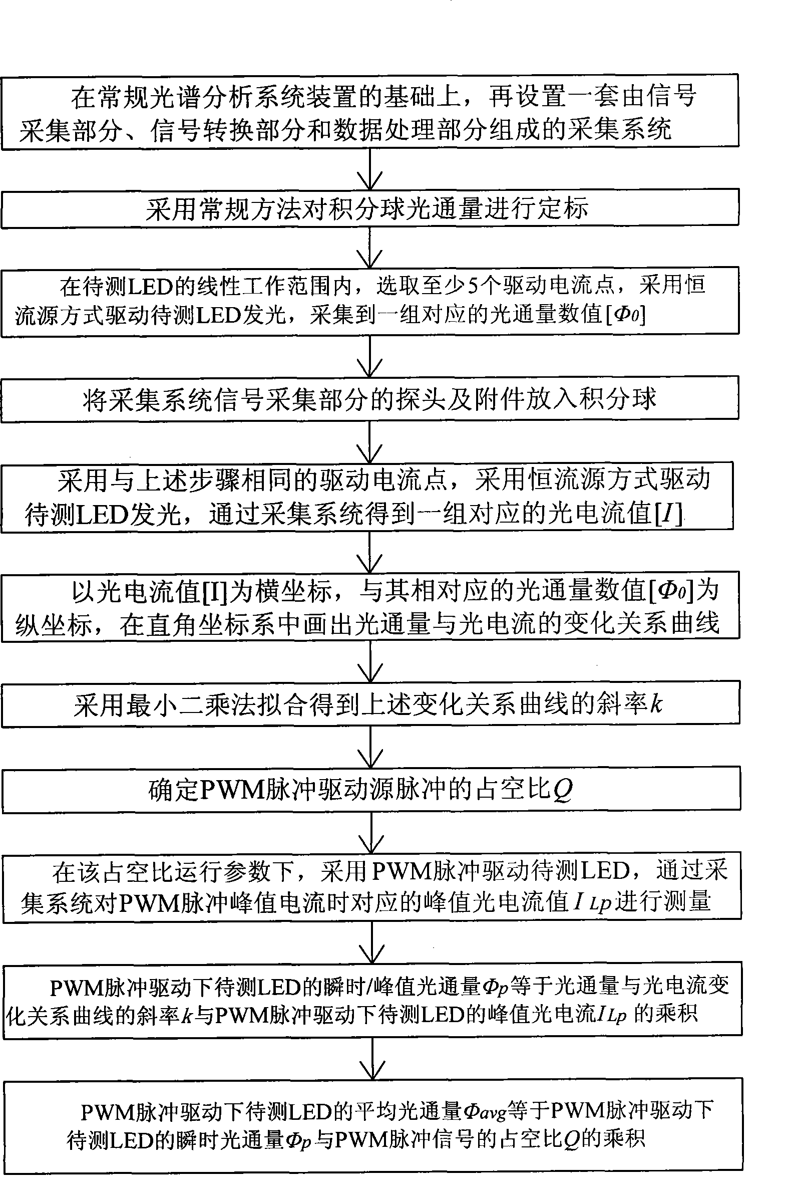
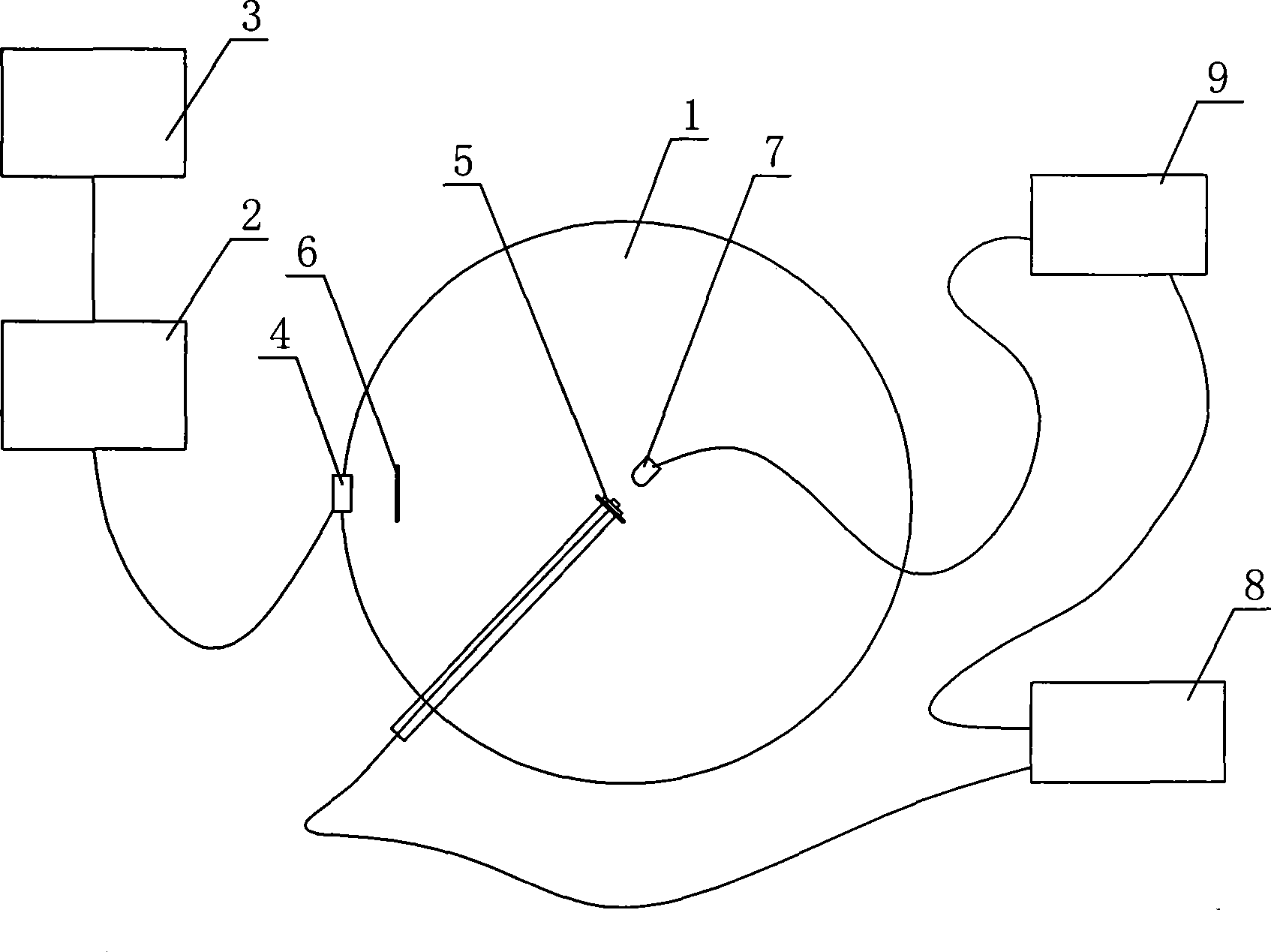
[0152] Using PMS-50 (enhanced) ultraviolet-visible-near-infrared spectral analysis system of Hangzhou Yuanfang Optoelectronics Information Co., Ltd. + 0.3m integrating sphere, the test is carried out according to the industry standard SJ2355.6-1983 "Integrating sphere measurement luminous flux calibration method". The specific process is as follows:
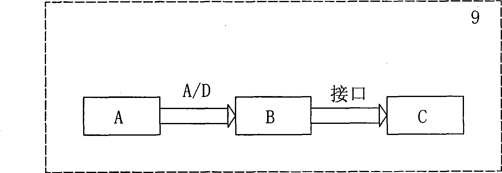
[0153] In preparation, press the figure 1 , figure 2 The connection relationship between the method and the device is set. In the experiment, a high-power white LED chip is selected, and a constant current is passed through it. The current is increased from 20mA to 400mA, and the relationship curve between the photocurrent of the photoelectric sensor and the luminous flux is obtained, as shown in Figure 8 shown.
[0154] It can be seen from the figure that within the linear range of the optical / electrical sensor, the photocurrent output of the optical / electrical sensor is proportional to the luminous flux, which is consisten...
PUM
 Abstract
Description
Claims
Application Information