Eureka AIR delivers breakthrough ideas for toughest innovation challenges, trusted by R&D personnel around the world.

Method for manufacturing optical film

A manufacturing method and technology of optical film, applied in the field of optical film, to achieve the effect of reducing left-right swing, stable conveying state, and less left-right swing

Active Publication Date: 2009-05-13
KONICA MINOLTA OPTO
View PDF26 Cites 9 Cited by
  • Summary
  • Abstract
  • Description
  • Claims
  • Application Information

AI Technical Summary

Problems solved by technology

[0014] In order to solve the above-mentioned conventional technical problems, the object of the present invention is to provide a manufacturing method of an optical film. With this method, even if a wide tape support is used to produce a film, there is little side-to-side oscillation, and a stable conveying state is maintained. Poor drying at the end of the cast film (sheet) and poor flatness of the film may occur, and stable high productivity can be obtained

Method used


Image

  • Method for manufacturing optical film
  • Method for manufacturing optical film
  • Method for manufacturing optical film

Examples


Embodiment 1~17

[0244] Embodiments 1 to 17 correspond to the inventions of claims 1 to 4. In order to manufacture a cellulose acetate propionate film with a target dry film thickness of 80 μm by using the solution casting method for making an optical film according to the present invention, first prepare the glue pulp.

[0245] (preparation of mucilage)

[0246] 100 parts by mass of cellulose acetate propionate

[0247] (The degree of substitution of acetyl group is 1.95, the degree of substitution of propionyl group is 0.7)

[0248] 10 parts by mass of triphenyl phosphate

[0249] 2 parts by mass of ethyl phthaloyl glycol

[0250] 300 parts by mass of dichloromethane

[0251]40 parts by mass of ethanol

[0252] TINUVIN 326 (manufactured by Ciba Specialty Chemicals) 1 part by mass

[0253] AEROSIL 200V (manufactured by Japan Aerosil Co., Ltd.) 0.1 parts by mass

[0254] Put the above materials into a sealed container in sequence, and after the temperature in the container is raised fro...

Embodiment 18~23

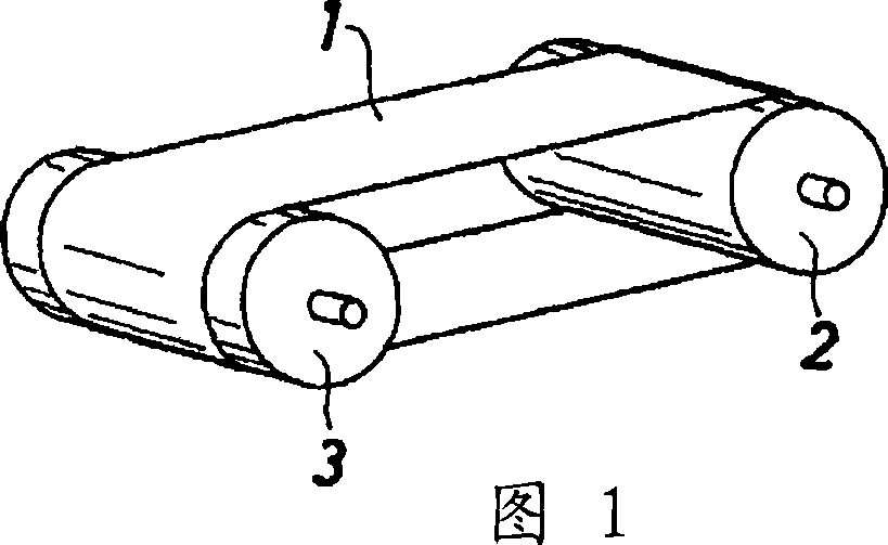
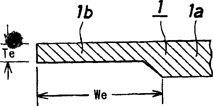
[0276] Examples 18 to 23 correspond to the inventions of claims 6 to 10, and prepared a tape test sample member (tape support) (11) having a total width of 500 mm and a length of 1000 mm. A sample part end portion (11b) is welded to one side edge of the sample part body (11a) of each test sample part (11).

[0277] As a material of the test sample member (11), SUS316 (longitudinal modulus of elasticity 220 [GPa]) was used. In addition, for the sample part end part (11b), two materials with different processing temperatures in SUS316 (longitudinal elastic modulus 220, 200 [GPa]), SUS304 (longitudinal elastic modulus 190 [GPa]), and SUS405 processing temperature were appropriately combined Different 2 kinds of materials (longitudinal elastic modulus 180, 175 [GPa]), adjust the longitudinal elastic modulus.

[0278] Here, as shown in Table 3 below, the width (We) of the sample member end portion (11b) is the width (We) of the test sample member (with support) (11) from one side ...


PUM

PropertyMeasurementUnit
widthaaaaaaaaaa
viscosityaaaaaaaaaa
reid vapor pressureaaaaaaaaaa

Abstract

Provided is a method for manufacturing an optical film having such a double refraction as can be used as the polarizing plate protecting film or the like for a liquid crystal display device (LCD). Even in case a wide belt support is used for the film production, the optical film manufacturing method can keep a less meandering stable transfer state to eliminate the poor drying of cast film (or web) end portions or the deterioration of a film flatness thereby to achieve a stable high productivity. In the manufacture of the optical film according to a solution-casting film forming method, the belt support has a width of 1.8 m or more, and the thickness (Te) of the two right and left end portions having a width (We) of 2 to 25 % of the whole belt support width (W) from the two side edges is smaller by 5 to 20 % than the thickness (T) of the remaining portion containing the widthwise central portion of the belt support. Alternatively, the modulus (Ee) of longitudinal elasticity of the two right and left end portions of the belt support is smaller by 5 to 20 % than the modulus (E) of longitudinal elasticity of the remaining portions containing the widthwise central portion of the belt support.

Description

technical field [0001] The present invention relates to optical films used in various display devices such as liquid crystal display devices (LCD) and organic EL (electroluminescence) display devices, especially protective films for polarizers used in these display devices, and can be used as retardation films A method for producing an optical film having birefringence. Background technique [0002] Generally, the basic configuration of a liquid crystal display device is to arrange polarizing plates on both sides of a liquid crystal cell. Polarizers only allow light passing through a polarized plane in a certain direction. Therefore, in liquid crystal display devices, they play an important role in visualizing liquid crystal orientation changes caused by electric fields. The performance of liquid crystal display devices is greatly affected by the performance of polarizers. [0003] In recent years, along with the enlargement of the screen of a liquid crystal panel, a wide p...

Claims


Application Information

Patent Timeline
Patent Type & Authority Applications(China)
IPC IPC(8): B29C41/28B29C41/38B29K1/00B29L7/00B29L11/00
CPCB29K2995/0034B29C41/28B29C41/38B29K2001/00B29L2011/00
Inventor 长嶋克佑
Owner KONICA MINOLTA OPTO
Why Eureka
Eureka Blog
Learn More