
Magnetic head substrate, magnetic head and recording medium driving device

A magnetic head and substrate technology, applied in the direction of magnetic recording, magnetic recording head, head hydrodynamic spacing, etc., can solve the problems of recording damage, strong thermal influence, etc., and achieve the goal of inhibiting threshing, inhibiting aggregation, and seeking uniformity of tissue Effect

Inactive Publication Date: 2009-05-13
KYOCERA CORP
View PDF3 Cites 0 Cited by
  • Summary
  • Abstract
  • Description
  • Claims
  • Application Information

AI Technical Summary

Problems solved by technology

However, if the floating amount of the magnetic head is small, the thermal influence generated by the coil of the electromagnetic conversion element of the magnetic head is relatively strong, which will cause the records stored in the recording medium to be destroyed.

Method used

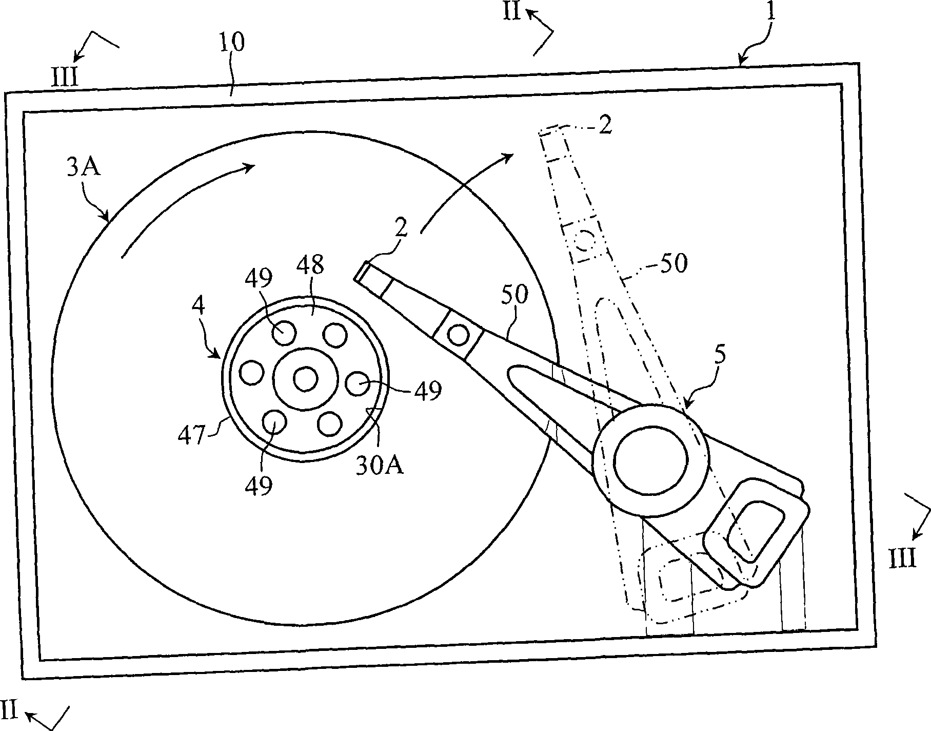
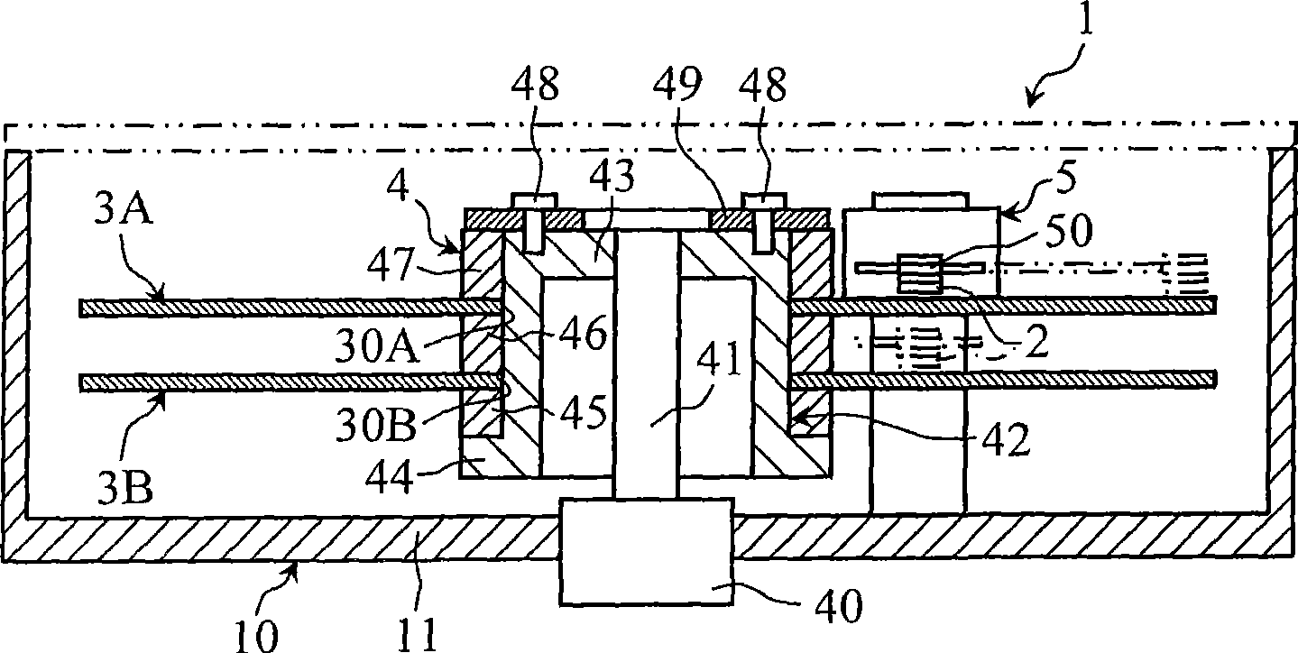
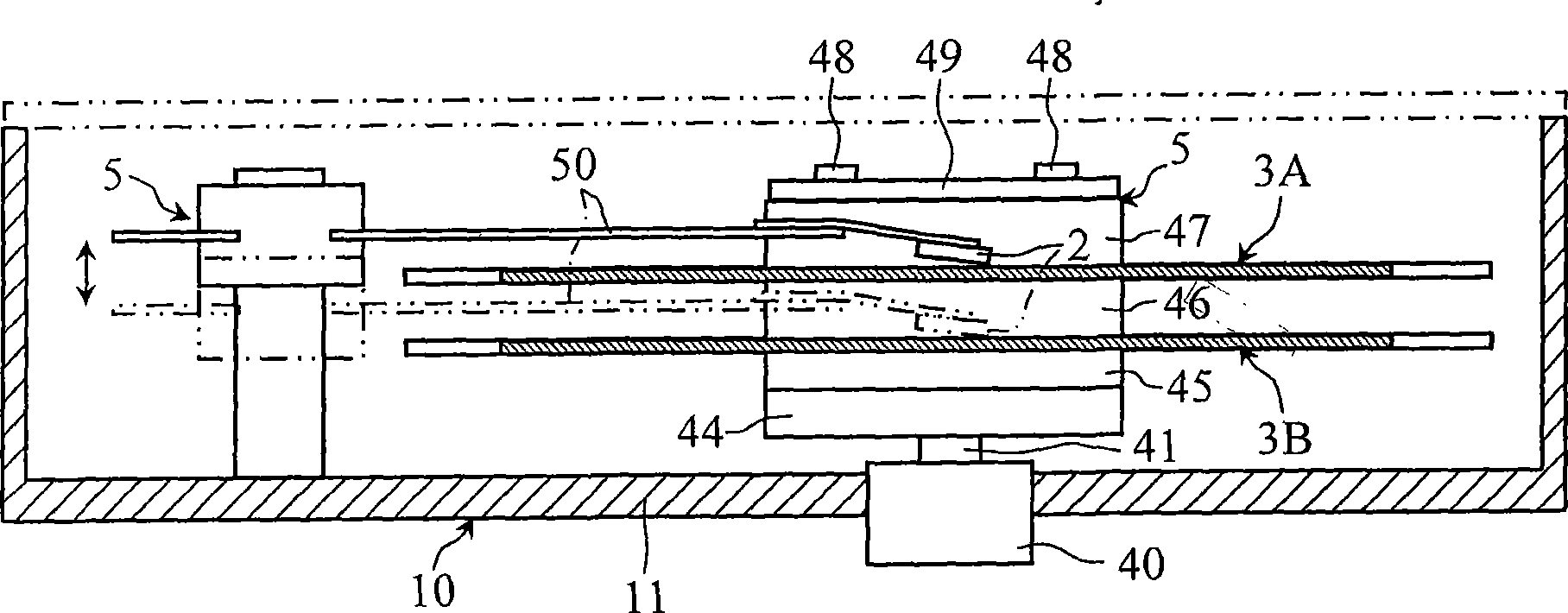

Image

  • Magnetic head substrate, magnetic head and recording medium driving device
  • Magnetic head substrate, magnetic head and recording medium driving device
  • Magnetic head substrate, magnetic head and recording medium driving device

Examples


Embodiment 1

[0120] In this example, a plurality of test pieces having different compositions and structural states were used to investigate the influence of the composition and the structural state on the mechanical properties.

[0121] (production of test piece)

[0122] For the test piece, a molded body was formed using abrasives containing material powder prepared with a desired composition, and the molded body was press-sintered to form a magnetic head substrate, and the magnetic head substrate was cut to produce a test piece.

[0123] As material powder, alumina, conductive compound and Yb are used 2 o 3 , and add a dispersant to these material powders.

[0124] Furthermore, by selecting the average particle size and content of alumina and conductive compound in the material powder, as shown in Table 1 below, the average crystal particle size and content. And the Yb of the material powder 2 o 3 The mass ratio of content is 0.2%.

[0125] After putting the abrasive into a spray...

Embodiment 2

[0147] In this example, the influence of the distribution density of the conductive compound in the test piece on the conductivity and mechanical properties was investigated.

[0148] (production of test piece)

[0149] A test piece was produced in the same manner as in Example 1. For the alumina and conductive compound particles of the sintered body (test piece), the average crystal grain size and content were adjusted as shown in Table 2, and the distribution density of the conductive compound particles of the test piece was adjusted by adjusting the firing temperature. On the other hand, the test piece was produced into a plate shape of 10 mm×2 mm and a long shape of 20 mm×50 mm×3.5 mm by cutting the sintered body.

[0150] (measurement of distribution density)

[0151] For the distribution density, the test piece was polished under the same conditions as in Example 1, and the number of conductive compound particles in the range of 20 μm×20 μm in the polished surface was ...


PUM

PropertyMeasurementUnit
flexural strengthaaaaaaaaaa
diameteraaaaaaaaaa
diameteraaaaaaaaaa

Abstract

Provided is a magnetic head substrate composed of a sintered body containing an alumina of 35 mass % or more but not more than 60 mass %, and a conductive compound of 40 mass % or more but not more than 65 mass %. The conductive compound includes at least one material selected from carbonate, nitride and carbonitride of tungsten. The maximum crystal grain diameter of the sintered body is 4[mu]m or less (excluding 0[mu]m). Furthermore, a magnetic head provided with a slider formed of the magnetic head substrate, and a recording medium driving device having such magnetic head are also provided.

Description

technical field [0001] The present invention relates to a magnetic head used in a recording medium drive such as a hard disk drive and a magnetic tape drive, and a substrate for a magnetic head used for a slider forming a base material of the magnetic head. Background technique [0002] Magnetic thin films are generally used as magnetic heads for recording and reproducing high-density magnetic disks. This magnetic head is required to have good abrasion resistance, and to have good surface smoothness, machinability, etc. on the floating surface. [0003] In order to manufacture this magnetic head, first in Al 2 o 3 - On a ceramic substrate made of TiC-based ceramics, a lower film made of amorphous alumina is formed by a sputtering method, and an electromagnetic conversion element is mounted on the lower film. The electromagnetic conversion element is used to exert the magnetoresistance effect. This electromagnetic conversion element is used, for example, in MR (Magnetro R...

Claims


Application Information

Patent Timeline
Patent Type & Authority Applications(China)
IPC IPC(8): G11B5/60G11B5/39C04B35/10G11B21/21G11B5/31
CPCC04B2235/5445C04B2235/3206C04B35/62655G11B5/3116C04B35/6263C04B2235/3847C04B35/488G11B5/3106C04B35/58007C04B2235/3217G11B5/6005C04B2235/963G11B5/3169C04B2235/5454C04B35/5626C04B2235/781G11B5/3173G11B5/3163C04B2235/3856C04B2235/96C04B2235/786C04B35/645C04B2235/656C04B2235/3224C04B2235/3225C04B2235/785C04B2235/3886B82Y30/00G11B5/6064G11B5/6082
Inventor 须惠敏幸中原正博源通拓哉
Owner KYOCERA CORP
Learn More