
Selective non-catalytic reduction method for gasifying and atomizing biomass and used boiler

A biomass and gasification technology, applied in chemical instruments and methods, separation methods, dispersed particle separation, etc., can solve the problems of low denitrification rate, single active ingredient, narrow temperature window, etc., and achieve simple boiler system and wide distribution , the effect of wide temperature window

Inactive Publication Date: 2009-05-20
HARBIN INST OF TECH
View PDF1 Cites 34 Cited by
  • Summary
  • Abstract
  • Description
  • Claims
  • Application Information

AI Technical Summary

Problems solved by technology

[0005] The purpose of the present invention is to solve the problems of narrow temperature window, low denitrification rate in the low temperature area and single active ingredient in the synthesis gas of reaction additives existing in the existing selective non-catalytic reduction method, and then provide a biomass gasification gas Atomized selective non-catalytic reduction method and boiler used

Method used

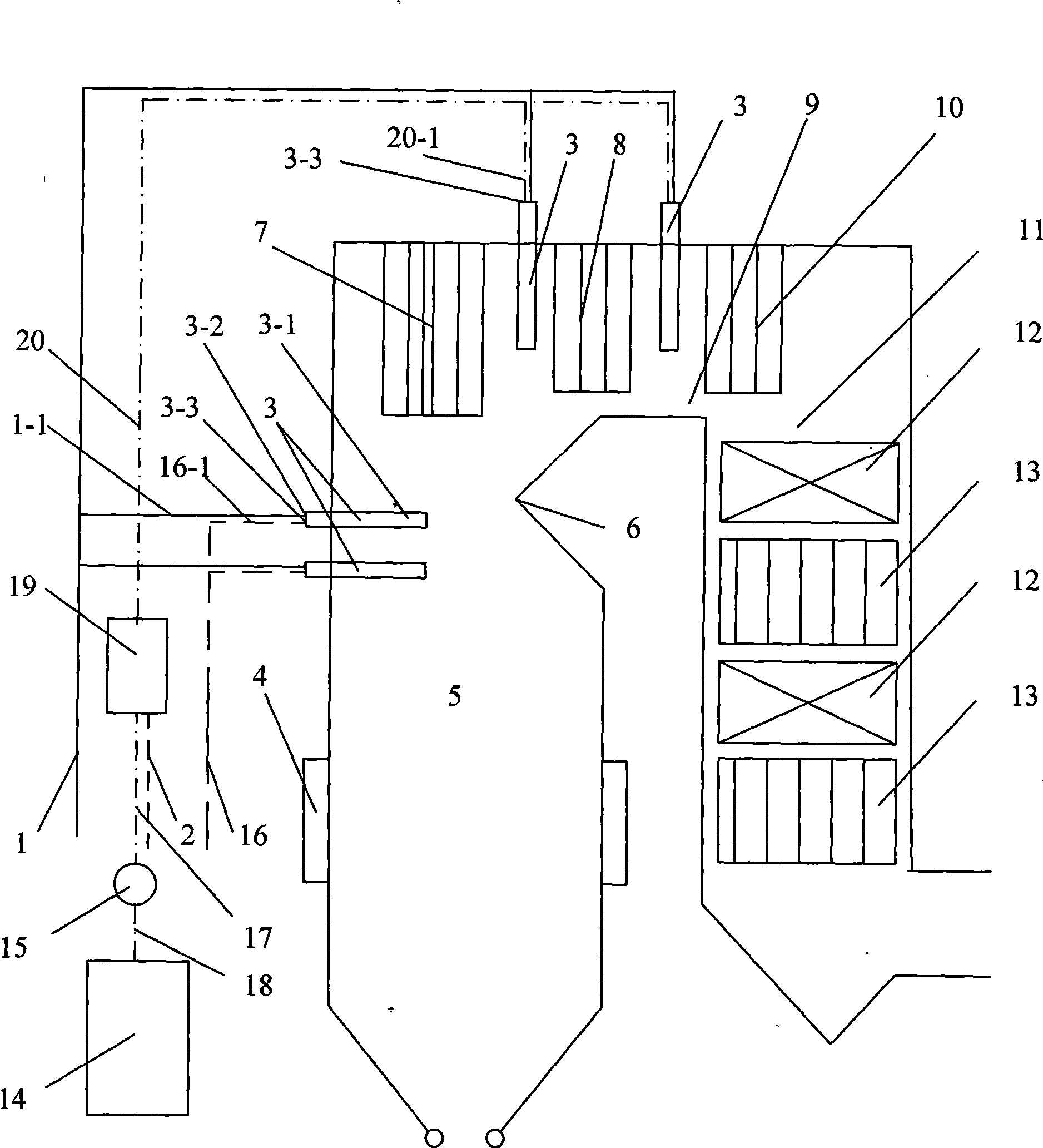
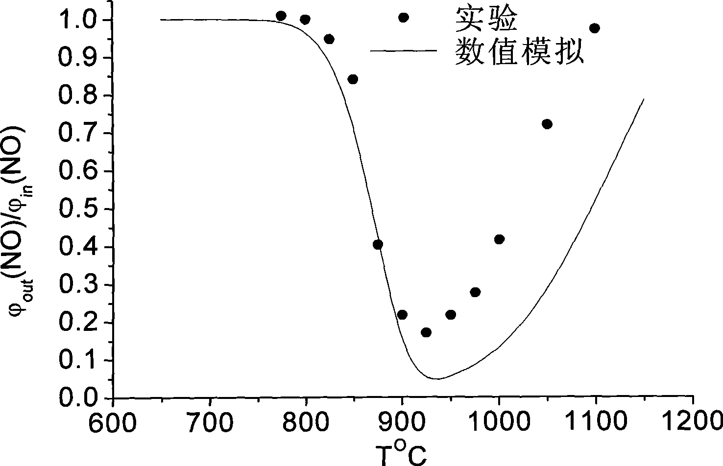
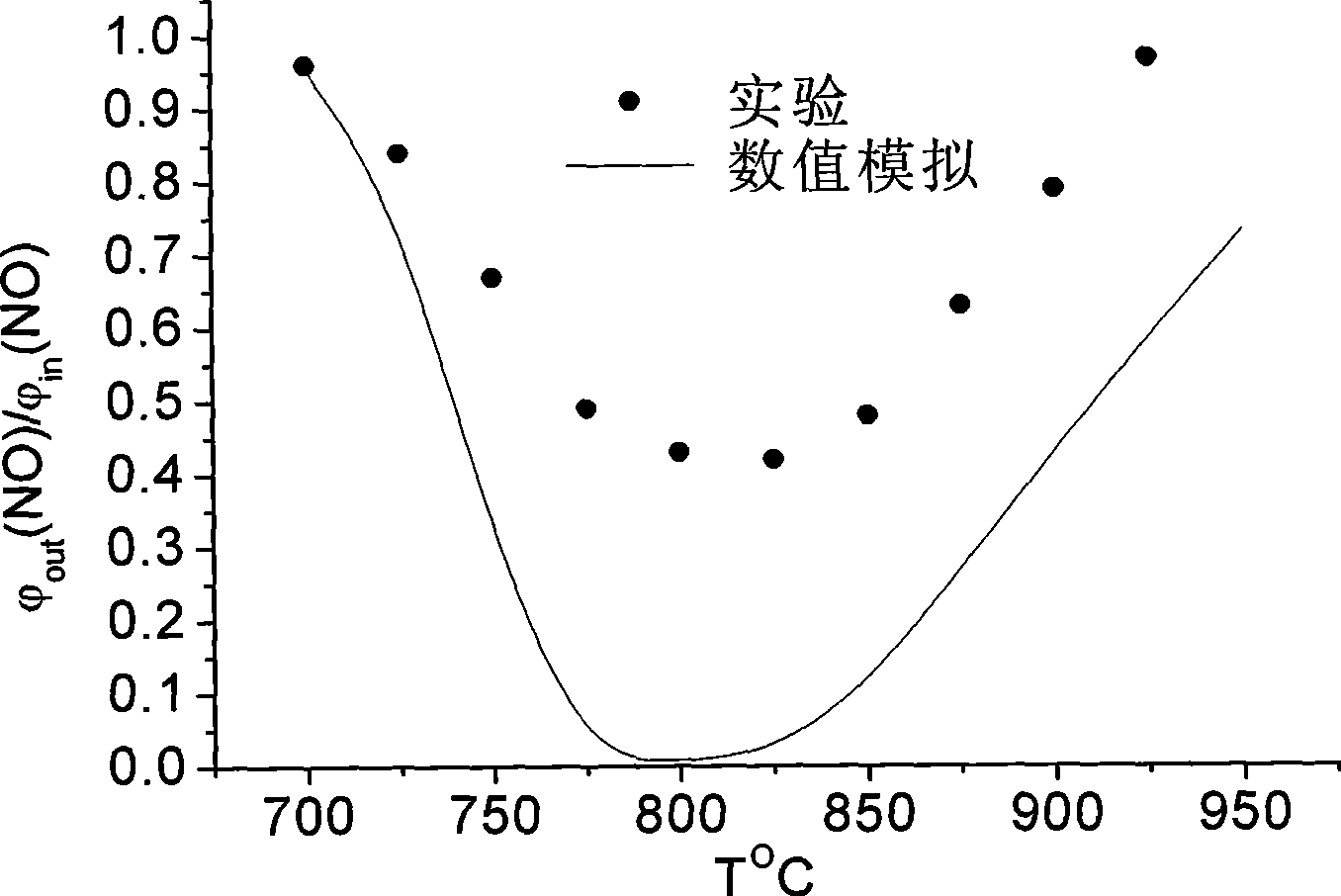

Image

  • Selective non-catalytic reduction method for gasifying and atomizing biomass and used boiler
  • Selective non-catalytic reduction method for gasifying and atomizing biomass and used boiler
  • Selective non-catalytic reduction method for gasifying and atomizing biomass and used boiler

Examples


specific Embodiment approach 1

[0010] Specific implementation mode one: combine figure 1 Describe this embodiment, this embodiment includes a body, a burner 4, a panel superheater 7, a high and low temperature superheater 8, a reheater 10, two economizers 12 and two air preheaters 13, the body It is made of a furnace 5, a horizontal flue 9 and a tail flue 11. The outer wall of the furnace 5 is equipped with a burner 4, the panel superheater 7, a high and low temperature superheater 8 and a reheater 10 along the flue The flow direction of the gas in the horizontal flue 9 is installed in the horizontal flue 9 in sequence, and the two economizers 12 and the two air preheaters 13 are arranged at the tail at intervals along the flow direction of the flue gas in the tail flue 11 In the flue 11, the boiler also includes an amino reducing agent solution pipeline 1, a compressed air pipeline 2, an atomizing air pipeline 16, a plurality of spray guns 3, a biomass gasification device 14, a pressurizing device 15, an ...

specific Embodiment approach 2

[0011] Specific implementation mode two: combination figure 1 Describe this embodiment, the selective non-catalytic reduction method of biomass gasification gas atomization of this embodiment is as follows: the amino reducing agent solution is filled in the amino reducing agent solution pipeline 1, and the amino reducing agent solution is injected into the amino reducing agent solution through a plurality of spray guns 3 Spray into the furnace 5 and the horizontal flue 9 near the refraction angle 6, the temperature range in the furnace 5 and the horizontal flue 9 near the refraction angle 6 is 900 ° C ~ 1100 ° C, using compressed air as the atomizing medium The atomized air pipeline 16 is sprayed into the furnace 5 and the horizontal flue 9 together with the ammonia reductant solution through the nozzle 3 arranged on the furnace 5 and the horizontal flue 9; the biomass produced by the biomass gasification device 14 is gasified The gas is charged into the biomass gasification ...

specific Embodiment approach 3

[0012] Specific embodiment three: the difference between this embodiment and specific embodiment two is: the total amount of the injection of the amino reducing agent solution is based on the NH produced by the reducing agent 3 The molar ratio of NOx in the flue gas before spraying with the amino reducing agent solution is 1.1-1.5. In this embodiment, the consumption of the amino reducing agent solution is equivalent to that of conventional SNCR, and the denitrification efficiency reaches 37-62% by adjusting the injection proportion of the amino reducing agent solution and biomass gasification gas.


PUM


Abstract

The invention relates to a selective non-catalytic reduction method for gasifying and atomizing biomass and a boiler used by the same, which relate to the selective non-catalytic reduction method and the boiler used by the same. The invention solves the problems that the prior selective non-catalytic reduction method has narrow temperature window, low denitration efficiency at a low temperature region and single effective component in synthesis gas of a reaction additive. The inlet of a gas mixer of the boiler is communicated with a gas additive pipeline and a compressed air pipeline respectively, while the outlet of the gas mixer is communicated with an atomizing medium pipeline. The selective non-catalytic reduction method mixes the biomass gasified gas in the gas additive pipeline with the compressed air through the gas mixer, uses the mixed gas as an atomizing medium for an amino reducing agent solution, and sprays the atomizing medium and the amino reducing agent solution together into a furnace chamber and a horizontal flue in a region with a temperature of between 800 and 950 DGE C through nozzles arranged in the furnace chamber and the horizontal flue. The selective non-catalytic reduction method improves the denitration efficiency and enlarges the temperature window. The boiler system of the invention is simple and has high reliability.

Description

technical field [0001] The invention relates to a selective non-catalytic reduction method and a used boiler. Background technique [0002] Nitrogen oxides (NOx) are one of the main air pollutants emitted by coal-fired boilers. In addition to forming acid rain and destroying the ecological environment, they can also form photochemical smog, which directly endangers human health. Since July 1, 2004, the state has charged 0.6 yuan per pollution equivalent of nitrogen oxides (the equivalent of nitrogen oxides is 0.95 kilograms) to directly charge the units that emit pollutants. It is imminent to control NOx emissions from coal-fired boilers. Currently controlling NO X Emission measures can be roughly divided into two categories, one is low NO X Combustion technology mainly includes low excess air operation technology, flue gas recirculation technology, thick-lean combustion technology and reburning combustion technology, etc. The cost of reburning technology at low NO X It...

Claims


Application Information

Patent Timeline
Patent Type & Authority Applications(China)
IPC IPC(8): B01D53/76B01D53/56F23J15/00
Inventor 刘辉吴少华曹庆喜朱舒扬黄霞苏俊伟郭浩然
Owner HARBIN INST OF TECH
Learn More