Self-adaptive elastic ring optical buffer for variable length optical packet

An optical buffer and optical grouping technology, applied in the field of optical communication, can solve the problems of poor upgrade ability and adaptability, increase the minimum granularity T of the cache, and poor cache flexibility, etc., and achieve powerful congestion control, traffic engineering, and flexible level The effect of linking and expanding capabilities and eliminating restrictions

Inactive Publication Date: 2009-06-03
BEIJING UNIV OF POSTS & TELECOMM
View PDF0 Cites 7 Cited by
  • Summary
  • Abstract
  • Description
  • Claims
  • Application Information

AI Technical Summary

Problems solved by technology

However, multiple cycles of the optical signal in the reflection path of the loop or FP cavity lead to the accumulation of ASE noise; the fixed loop length limits the length of the optical packet (in order to ensure that the head and tail of the optical packet do not overlap, the packet length must not be greater than the corresponding loop length); in order to meet the buffer requirements of the longest optical packet in the network, only the loop length or the reflection path length of the FP cavity can be increased, but this increases the minimum granularity T of the cache, resulting in poor cache flexibility
When the network is upgraded or changed, the feedback structure needs to change the length of the entire optical fiber in the cache, so the upgrade ability and adaptability are poor

Method used


Image

  • Self-adaptive elastic ring optical buffer for variable length optical packet
  • Self-adaptive elastic ring optical buffer for variable length optical packet
  • Self-adaptive elastic ring optical buffer for variable length optical packet

Examples


Embodiment 1

[0030] The caching function of the single-level buffer is implemented as follows:

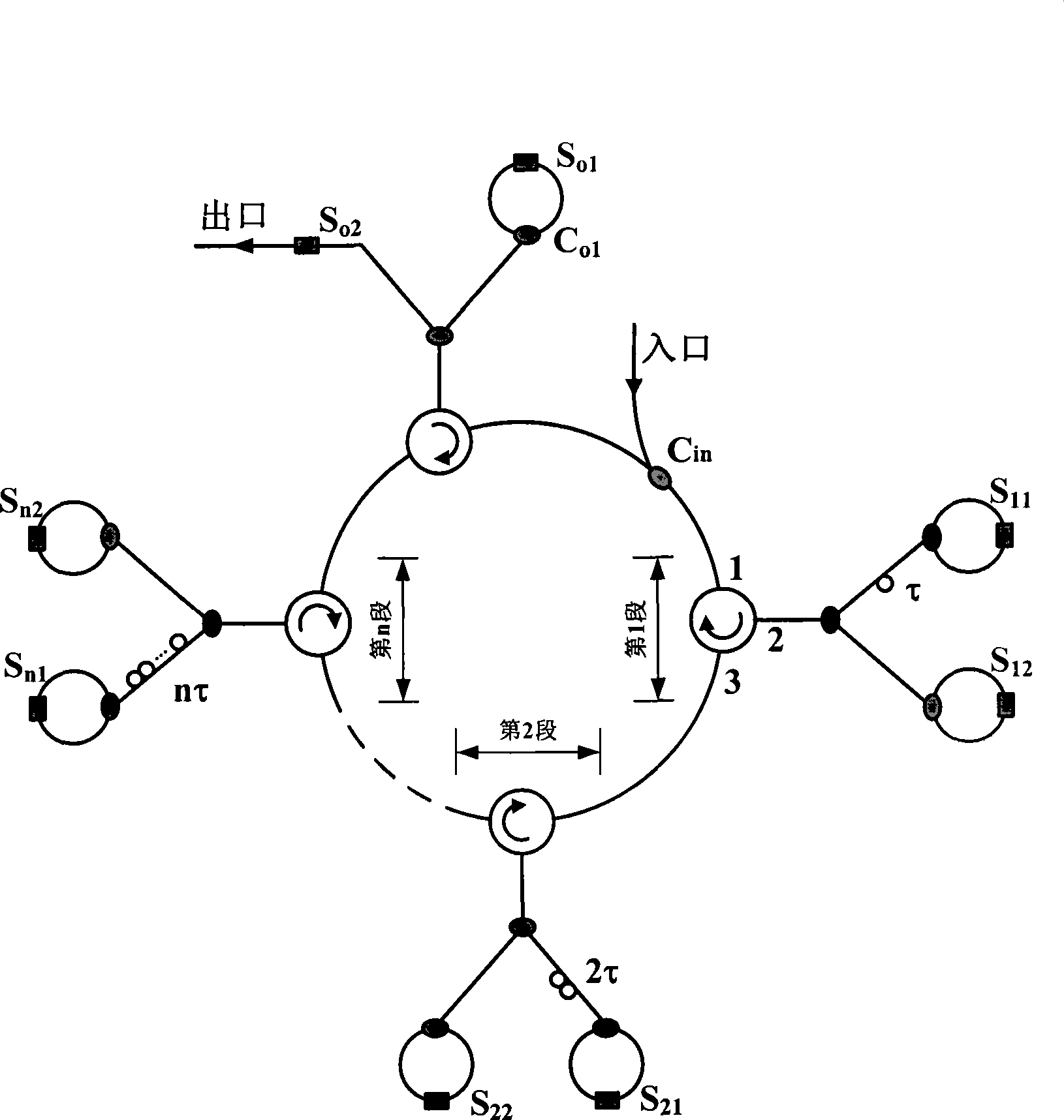
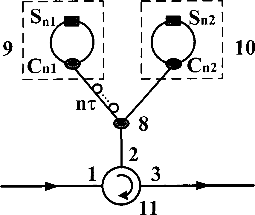
[0031] like figure 2 shown, setting S n1 Open S n2 off, the basic buffer unit completes the function of buffering optical packets for 2nτ; set S n1 Close S n2 On, the basic cache unit completes the non-caching function. Similarly, if Figure 4 As shown in the buffer exit structure, set S o1 Open S o2 Off, optical packets will continue to be buffered in the buffer; set S o1 Close S o2 On, the optical packet will be read out of the buffer. Therefore, if figure 1 As shown, for each basic buffer unit and outlet in the buffer, a pair of reverse electrical signals are used to control the buffer delay combination function and the buffer cycle number selection function of the buffer. E.g:

[0032] ①Set S in the first basic cache unit 11 Open S 12 Off, all others are set to S n1 Close S n2 open, the exit is S o1 Close S o2 On, the optical packet will be buffered in the buffer for 2τ t...

Embodiment 2

[0041] The caching function of the system-level cascaded buffer is realized in the following way (the cache structure is as follows Image 6 shown):

[0042] 1) The internal control mode of each level of buffer is the same as that of Embodiment 1;

[0043] 2) The two-way transmission capability of the ring structure and the separate "read / write" function enable the buffer to allow the optical packets in the rear to be directly output counterclockwise when buffering the optical packets without affecting the optical packets being buffered. For example: assuming that there are optical packets in the cache in the first-level and second-level buffers, when the optical packets in the second level are still in the buffer state, the optical packets in the first level can enter the first level through the exit of the first level. The entrance of level 2, and the counterclockwise direct output, enters the level 3 buffer. Where the length of the optical packet in the first level is l ...


PUM


Abstract

A self-adaptive elastic ring optical buffer for a variable length optical packet includes an annular structure consisting of basic buffer units with different buffer delays, wherein the on / off state of the basic buffer unit determines whether the optical packet is buffered in the unit, and the on / off control optical packet at the outlet is continuously buffered or read out. The selection of the number of turns of the buffer and the buffer unit can enable the self-adaptive elastic ring optical buffer to be adapted to optical packet buffer with arbitrary lengths, thereby obviating the restriction of a feedback structure on the length of the optical packet. In addition, the self-adaptive elastic ring optical buffer has larger buffer delay change range, bidirectional delay dynamic reconstruction capability, optional delay budget and more compact structure in comparison with a feedforward structure. The separated read-write control and the annular structure can ensure the optical packet in the buffer to be directly read out without influencing the buffering optical packet, so that the cascade structure has a plurality of queuing functions. Based on fiber delay line and SOA gain switch, the self-adaptive elastic ring optical buffer also has the advantages of nanosecond-scale reconstruction capability, lower ASE noise accumulation and power loss, low cost, high stability, simple implementation, etc.

Description

technical field [0001] The invention relates to an optical buffer based on an optical fiber delay line, especially an adaptive elastic ring buffer structure capable of adapting to different optical packet lengths. The optical buffer is a key component for realizing a high-performance all-optical packet switching network, and belongs to the technical field of optical communication. Background technique [0002] The optical buffer is used to realize the temporary storage function of signals in optical information processing, and is a key component for realizing high-performance packetized optical switching nodes. In a packetized optical network, the all-optical buffer is not only the most effective means to solve the problem of optical packet congestion, realize traffic engineering and ensure QoS, but also realize node label extraction and routing selection, line-speed read-in and variable-speed read-out, and optical An essential component for group synchronization and other ...

Claims


Application Information

Patent Timeline
Patent Type & Authority Applications(China)
IPC IPC(8): H04Q11/00H04B10/12G02B6/28
Inventor 王宏祥宫小卉纪越峰
Owner BEIJING UNIV OF POSTS & TELECOMM
Why Eureka
Try Eureka