Exhaust-heating boiler and furnace body thereof

A waste heat boiler and furnace body technology, applied in steam boilers, water tube steam boilers, steam generation methods using heat carriers, etc., can solve the problems of reduced waste heat recovery efficiency, low heat recovery efficiency, time-consuming cleaning operations, etc. The effect of improved recycling efficiency, improved efficiency, and reduced ash deposition

Inactive Publication Date: 2009-06-10
CHINA ENFI ENGINEERING CORPORATION
View PDF1 Cites 8 Cited by
  • Summary
  • Abstract
  • Description
  • Claims
  • Application Information

AI Technical Summary

Problems solved by technology

The dust (such as slag) contained in the high-temperature flue gas is very easy to stick to the inner wall of the furnace body. Therefore, the furnace needs to be cleaned frequently. For the dust deposited on the inner wall of the furnace, the cleaning operation is time-consuming and laborious.
Moreover, due to dust sticking to the inner wall of the furnace body, the life of the furnace body is reduced, and the waste heat recovery efficiency is reduced
In addition, the flue gas tends to flow directly from the smoke inlet to the smoke outlet, so that the residence time in the furnace is short and the heat recovery efficiency is low

Method used


Image

  • Exhaust-heating boiler and furnace body thereof
  • Exhaust-heating boiler and furnace body thereof
  • Exhaust-heating boiler and furnace body thereof

Examples


Embodiment Construction

[0034] Embodiments of the present invention are described in detail below, examples of which are illustrated in the accompanying drawings, wherein like reference numerals refer to like elements throughout. The embodiments described below are used to explain the present invention by referring to the figures, and the embodiments are exemplary and should not be construed as limitations of the present invention.

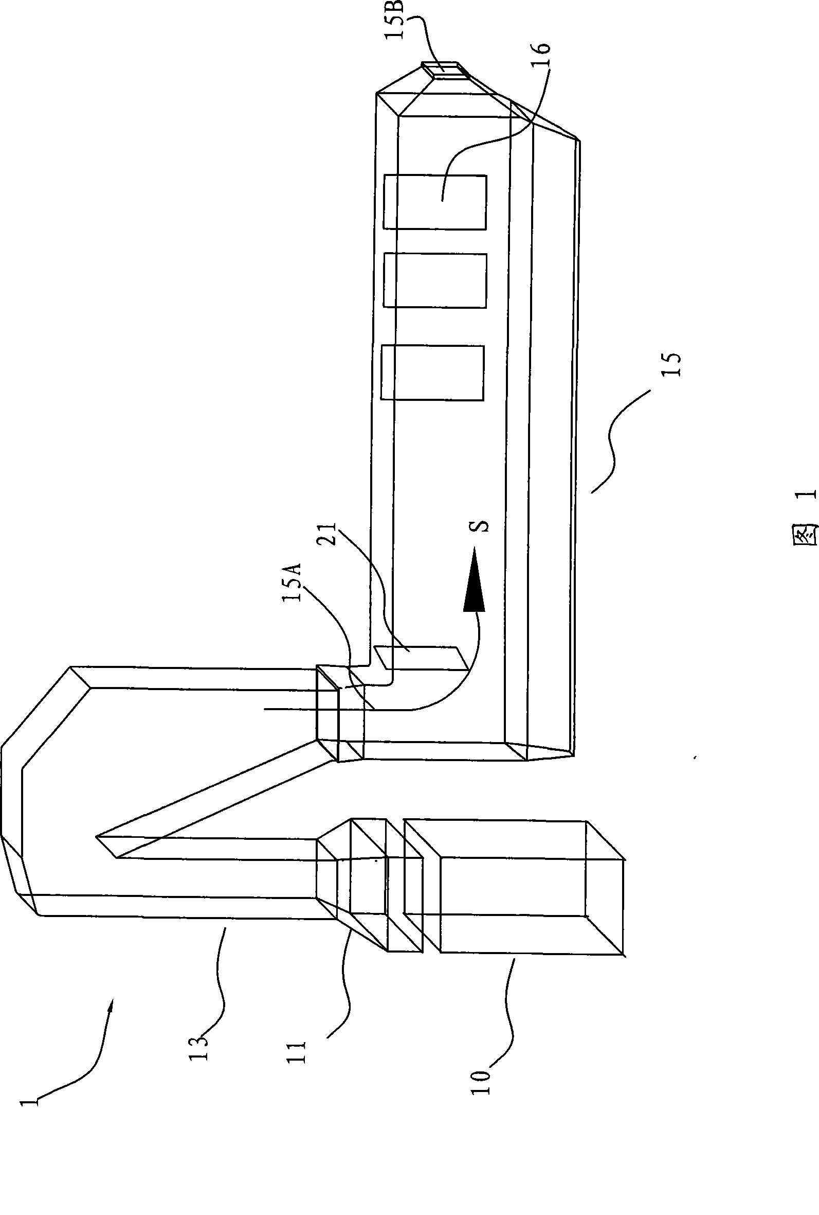
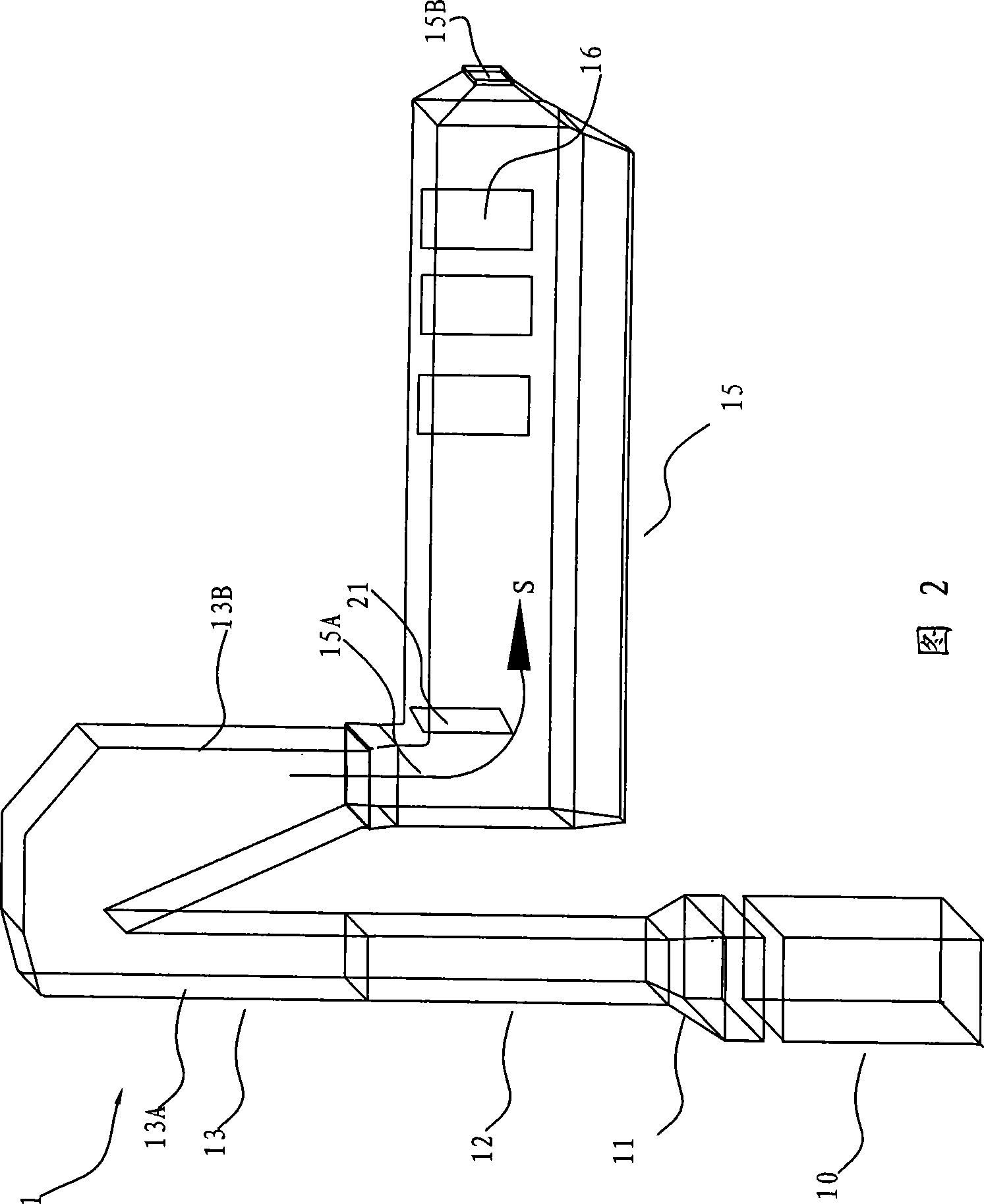
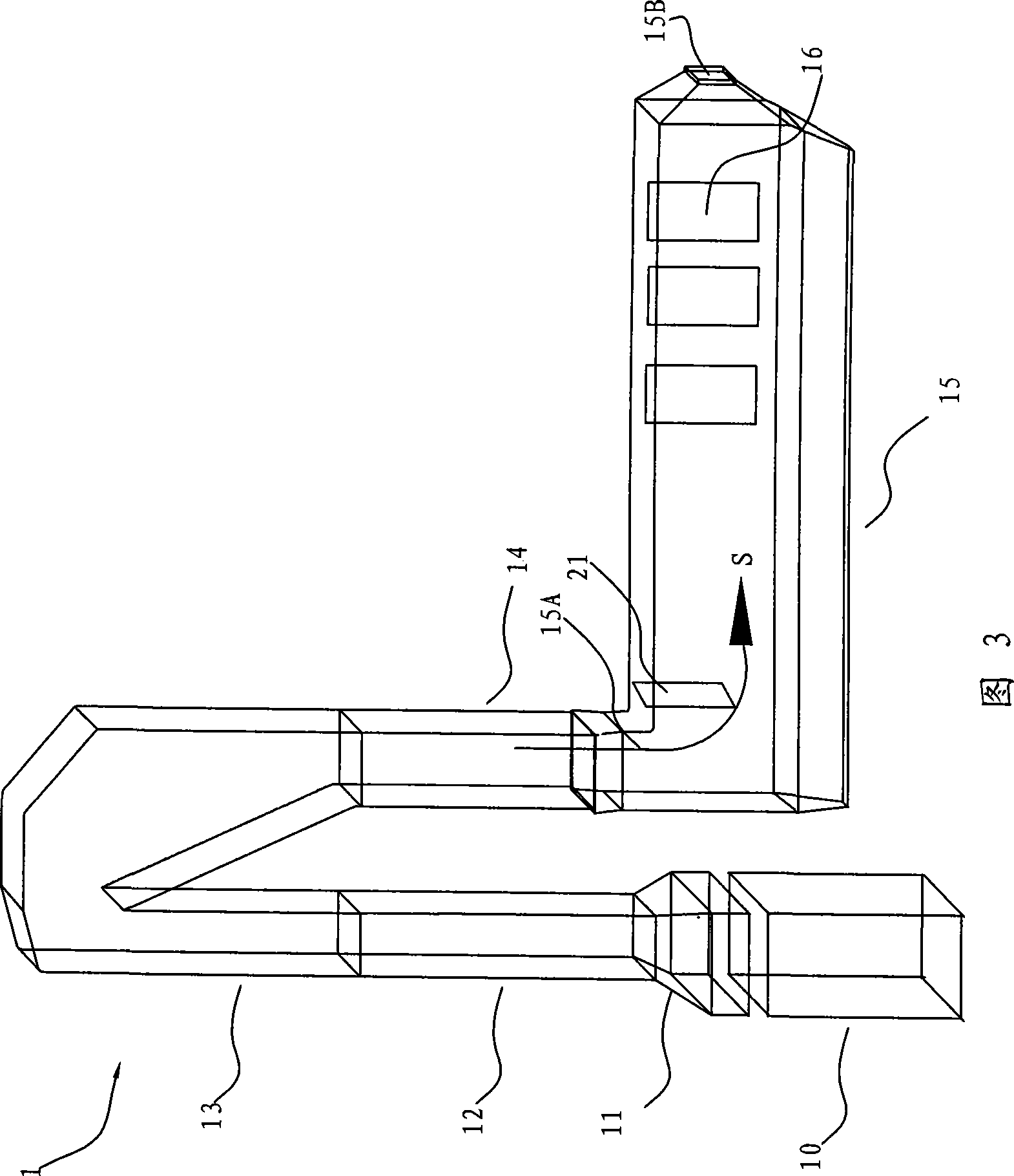
[0035] Firstly, the furnace body of the waste heat boiler according to the embodiment of the present invention will be described below with reference to FIG. 1 . FIG. 1 is a schematic diagram of the furnace body of the waste heat boiler according to the embodiment of the present invention.

[0036] The waste heat boiler furnace body 1 according to the embodiment of the present invention includes a transition section flue 13 and a convection section flue 15, the transition section flue 13 includes an ascending portion 13A and a descending portion 13B, and the top of the as...


PUM


Abstract

The invention discloses a body of waste heat boiler, comprising a transition section flue which comprises an ascending part and a descending part, wherein, the top end of the ascending part is connected with the top end of the descending part, and a convection section flue, wherein, a smoke inlet of the convection flue is connected with the lower end of the descending part of the transition section flue and a smoke outlet forms at the smoke discharging end of the convection section flue. According to the boiler body of the invention, since the transition section flue is arranged, high temperature flue gas containing dust enters into the ascending part of the transition section flue from a melting furnace and the dust contained in the high temperature flue gas can fall by depending on gravity during ascending process, thus the dust is not easy to stick on inner wall of the boiler body and accumulated dust is light in the boiler body, thus reducing dust removal operation, improving service life of the boiler body, prolonging operation time of the high temperature flue gas in the boiler body and improving recycling efficiency of the waste heat.

Description

technical field [0001] The invention relates to a waste heat boiler and its furnace body, in particular to a waste heat boiler and its furnace body used for smelting furnaces. Background technique [0002] Waste heat boilers are equipment used to recover heat. For example, in the field of nonferrous metallurgy, waste heat boilers are widely used to recover the heat in the flue gas of smelting furnaces. [0003] In the prior art, the furnace body of the waste heat boiler is generally composed of a single parallelepiped or column, and the furnace body forms a furnace. [0004] The Chinese utility model patent CN2354093Y discloses a waste heat boiler. The furnace body of the waste heat boiler is a parallelepiped, and a steam drum is arranged on the furnace body. The flue gas enters from one side of the furnace body and exits from the opposite side. [0005] In the prior art including the waste heat boiler mentioned above, high-temperature flue gas enters from one side of the ...

Claims


Application Information

Patent Timeline
IPC IPC(8): F22B1/16F22B21/34F22B37/34
Inventor 徐建炎王岗陈逢胜张计鹏
Owner CHINA ENFI ENGINEERING CORPORATION
Why Eureka
Try Eureka