Submerge liquid supplying recovery controlling device for photoetching machine

A technology of liquid supply and control device, which is applied in the direction of photolithography exposure device, microlithography exposure equipment, etc. It can solve the problems of affecting the stable operation of the exposure system, difficult coordination of pressure, and negative exposure quality, so as to achieve timely and effective contamination and temperature rise, reduce the infiltration of boundary bubbles, and eliminate the effects of flow field interference and pollution

Inactive Publication Date: 2009-06-10
ZHEJIANG UNIV +1
View PDF3 Cites 12 Cited by
  • Summary
  • Abstract
  • Description
  • Claims
  • Application Information

AI Technical Summary

Problems solved by technology

[0006] (1) Due to the use of positive pressure liquid supply and negative pressure recovery, the pressures of the two are not easy to coordinate, and it is easy to cause pressure fluctuations and interference forces in the filling flow field, and lead to turbulent flow in the liquid and some undesirable and unpredictable effects
[0007] (2) The existing air sealing method uses an air curtain to apply around the filling fluid, causing instability at the edge of the flow field. During the high-speed stepping and scanning process of the substrate, it may cause liquid leakage and entrainment of sealing gas to the flow field At the same time, gas-liquid two-phase flow will be formed when the filling liquid and sealing gas are recovered, which will cause vibration and affect the stable operation of the exposure system
During the high-speed movement of the substrate, once the external air or sealing liquid is involved or dissolved or diffused into the filling liquid, it will have a negative impact on the exposure quality
[0009] (4) When the substrate is moving at a high speed, due to the effect of molecular adhesion, the liquid close to the substrate will move along with the substrate, and thus the receding contact angle opposite to the moving direction of the substrate will become smaller, making Boundary liquid is more likely to be pulled to the periphery of the flow field, causing liquid leakage, and thus forming a series of defects (such as: water marks)

Method used


Image

  • Submerge liquid supplying recovery controlling device for photoetching machine
  • Submerge liquid supplying recovery controlling device for photoetching machine
  • Submerge liquid supplying recovery controlling device for photoetching machine

Examples


Embodiment Construction

[0034] The present invention will be further described below in conjunction with the accompanying drawings and embodiments.

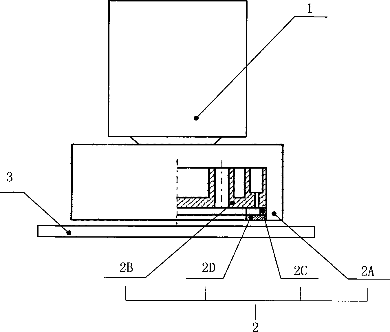
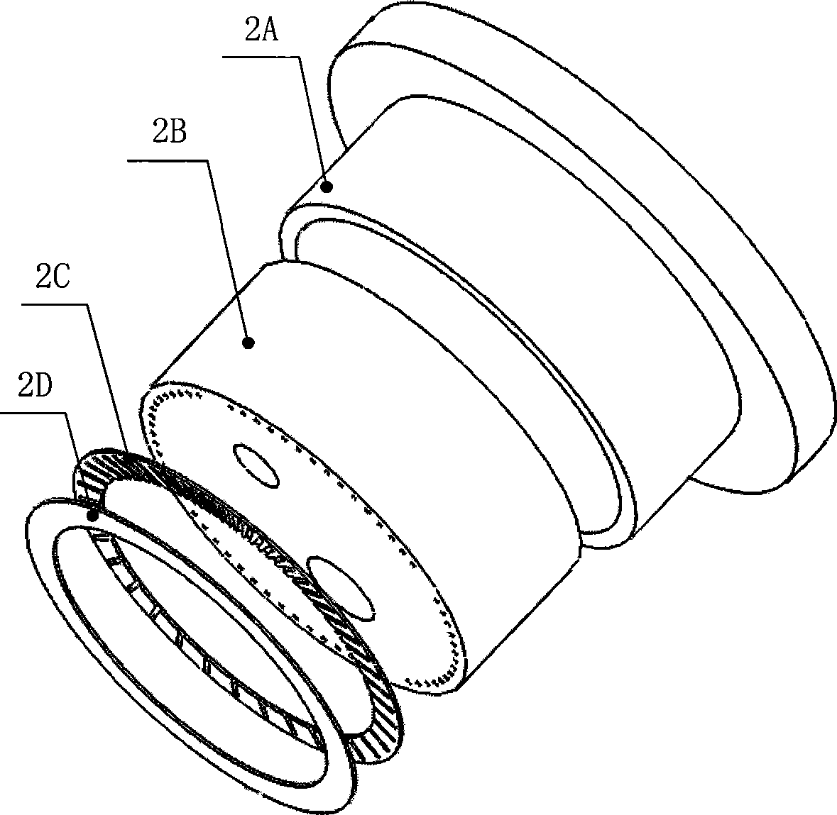
[0035] Such as figure 1 , figure 2 As shown, the present invention is a liquid supply and recovery control device 2 arranged between the projection lens group 1 and the substrate 3 . The liquid supply and recovery control device 2 includes a liquid injection cover 2A, a liquid injection tray 2B, a flow control ring 2C and a retaining ring 2D; wherein:

[0036] 1) Liquid injection cover 2A: from the center to the outside, there is an external connection channel 6B of the recovery chamber offset from the center, and two symmetrically distributed liquid injection chambers external connection channel 6A;

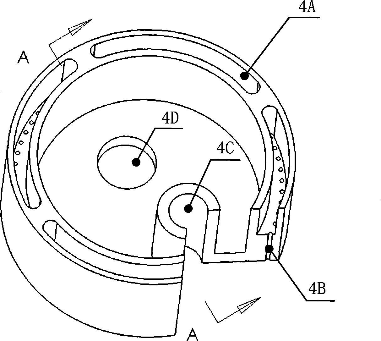
[0037] 2) Liquid injection plate 2B: the objective lens hole 4D offset from the center outwards, the recovery chamber 4C and four liquid injection chambers 4A uniformly arranged in a ring along the circumferential direction, and the four liquid injecti...


PUM


Abstract

The invention discloses an immersion liquid supply and recovery control device for a mask aligner. The immersion liquid supply and recovery control device is arranged between a projection lens group and a substrate to be exposed and consists of a liquid charging cover, a liquid charging disc, a flow control loop and a retainer ring. The external liquid charging and the internal liquid recovery are adopted. Liquid enters a slit flow field from the periphery with the fixed quantity and in the mode of high speed injection; and the balance and stability of the whole flow field is realized through coordination and control of the negative pressure acting on an internal recovery cavity. The mode of high speed liquid injection from outside to inside can not only effectively counteract the internal power of outward liquid leakage and reduce the infiltration of boundary air bubbles caused by a gas sealing device, but also quicken the updating rate of the flow field and consequently facilitate the timely removal of pollutants produced in the process of exposure.

Description

technical field [0001] The invention relates to an immersion liquid supply and recovery control device in an immersion lithography (Immersion Lithography) system, in particular to an immersion liquid supply and recovery control device for a photolithography machine. Background technique [0002] Modern lithography equipment is based on optical lithography, which uses an optical system to accurately project and expose the pattern on the mask onto a substrate (such as a silicon wafer) coated with photoresist. It includes a laser light source, an optical system, a projection mask composed of chip patterns, an alignment system and a substrate covered with photosensitive photoresist. [0003] The immersion lithography system fills a certain liquid in the gap between the projection lens and the substrate, and increases the numerical aperture (NA) of the projection lens by increasing the refractive index (n) of the medium in the gap, thereby improving the resolution of lithography ...

Claims


Application Information

Patent Timeline
Patent Type & Authority Applications(China)
IPC IPC(8): G03F7/20
Inventor 杨华勇陈文昱巴静傅新李小平
Owner ZHEJIANG UNIV
Why Eureka
Try Eureka