Composite graphite heat conducting radiation fins

A composite graphite and graphite heat conduction technology, which is applied in the field of heat conduction and heat dissipation materials and heat conduction materials, and can solve the problems of complex operation, weak firmness, and weak bonding.

Inactive Publication Date: 2009-06-17
王晓山
View PDF0 Cites 37 Cited by
  • Summary
  • Abstract
  • Description
  • Claims
  • Application Information

AI Technical Summary

Problems solved by technology

The traditional bonding method is to bond the graphite heat sink with glue. This bonding method is more complicated to operate and requires specific operations during bonding, which may cause uneven bonding caused by uneven glue. firm question
At the same time, due to the fragile nature of graphite, sometimes it is necessary to bond metal sheets o

Method used


Image

  • Composite graphite heat conducting radiation fins
  • Composite graphite heat conducting radiation fins
  • Composite graphite heat conducting radiation fins

Examples


Example Embodiment

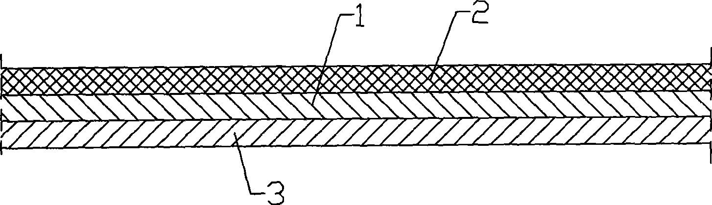
[0026] Embodiment 1, a composite graphite heat-conducting heat sink, comprising an intermediate layer 1 formed by a pure graphite heat-conducting heat sink, one of the surfaces of the intermediate layer 1 is provided with a back glue layer 2, and the graphite of the composite graphite heat-conducting heat sink is made, Generally, anisotropic graphite sheets with high thermal conductivity should be used, and the thickness of graphite should be between 0.067mm and 2.0mm. In general, when the thickness of graphite is greater than 2.0mm, there is no need to make a composite type, and it can be directly Manufactured into an anisotropic graphite heat-conducting heat sink, the graphite density is selected according to the high and low requirements of the thermal conductivity, and the other side of the intermediate layer corresponding to the adhesive layer is provided with a PET film 3. The thickness is 0.01mm~0.04mm, and the temperature resistance range is between -30℃~+250℃.

[0027...

Example Embodiment

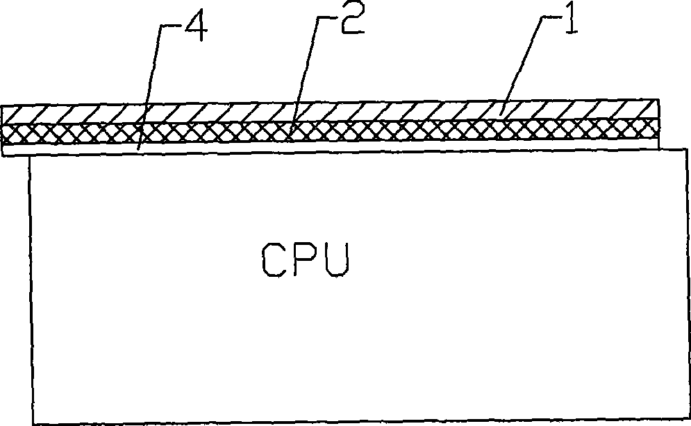
[0028] Embodiment 2: a composite graphite heat-conducting heat sink, comprising an intermediate layer 1 formed by a pure graphite heat-conducting heat sink, one surface of the intermediate layer 1 is provided with a back glue layer 2, and the middle layer 1 and the back glue layer 2 are provided. The corresponding other side is provided with copper foil or aluminum foil. Generally, copper foil with a thickness of 0.02mm to 0.05mm or aluminum foil with a thickness of 0.01mm to 0.04mm is used. figure 2 It is a schematic diagram of the specific application of the composite graphite heat-conducting heat sink. This is a composite type of anisotropic graphite heat-conducting heat sink with adhesive 2 bonded on one side, a graphite sheet on the middle layer 1, and copper foil 4 on the other side applied to computers. A physical legend on CPU5. The graphite sheet 1 and the copper foil 4 are firmly bonded to the CPU casing through the adhesive 2, and the heat emitted by the CPU passes...


PUM

PropertyMeasurementUnit
Thicknessaaaaaaaaaa
Thicknessaaaaaaaaaa
Heat resistantaaaaaaaaaa

Abstract

The invention discloses a combined graphite heat conducting radiating fin which comprises an intermediate layer formed by a pure-graphite heat conducting radiating fin. One surface of the intermediate layer is provided with a gum layer which increases the strength of a soft graphite sheet and prevents the graphite sheet from generating bug dust and influencing the appearance and the use, and the gum layer also betters bending capability; and a three-dimensional assembly can be processed, thereby further facilitating the processing of a graphite heat conducting radiating material with any size, any shape and any structure and enlarging use range of the graphite sheet. By adopting the anisotropic graphite heat conducting radiating fin, the efficiency in heat conduction and radiation is high, small area is occupied, the weight is light, the heat is uniformly conducted and radiated, heat point areas are eliminated, and the performance of an electronic product is improved when a heat source is isolated from components.

Description

technical field [0001] The invention relates to a heat-conducting material, especially a heat-conducting and heat-dissipating material used in electronic products, in particular to a composite graphite heat-conducting heat sink. Background technique [0002] With the acceleration of the continuous upgrading of electronic products and the increasing growth of high-integration and high-performance electronic devices, the size of working components is getting smaller and smaller, the speed and efficiency of work are getting higher and higher, and the heat generation is getting bigger and bigger. At present, the known metal heat-conducting and heat-dissipating components have been limited by their materials and their own heat-conducting and heat-dissipating limits. Advanced heat-conducting and heat-dissipating processes and excellent heat-conducting and heat-dissipating materials must be used to effectively remove heat and ensure the effective work of their electronic products. ...

Claims


Application Information

Patent Timeline
IPC IPC(8): F28F3/00B32B9/04B32B27/36B32B15/20
Inventor 王晓山
Owner 王晓山
Why Eureka
Try Eureka