Electrical power system failure information obtaining method

A technology of fault information and acquisition method, which is applied to fault locations, electrical components, circuit devices, etc., and can solve problems such as low sampling frequency and inability to meet traveling wave ranging.

Active Publication Date: 2009-06-17
SHANDONG KEHUI POWER AUTOMATION
View PDF0 Cites 40 Cited by
  • Summary
  • Abstract
  • Description
  • Claims
  • Application Information

AI Technical Summary

Problems solved by technology

Although optical fiber TV and optical fiber TA, which are the future development directions, can transmit high-frequency traveling wave

Method used


Image

  • Electrical power system failure information obtaining method
  • Electrical power system failure information obtaining method
  • Electrical power system failure information obtaining method

Examples


Embodiment 1

[0110] 1. Utilize transient fault information mainly based on zero-mode components to locate small current ground fault sections

[0111]Utilizing the present invention to realize the location of the small current grounding fault section may be a fault indicator with a single function, and the FTU may also be used instead of the fault indicator as the core processing unit, collectively referred to as a fault indicating device. A typical automatic fault location system consists of three parts: a fault indication device distributed at each detection point of the line, a communication network (such as GPRS, etc.), and a master station of the automatic fault location system. The fault indication device collects the fault voltage and current information output by the electric field and magnetic field sensors. After a fault occurs, the component of the fault information in the characteristic frequency band is used to calculate the fault direction, and the fault indication device rep...

Embodiment 2

[0123] 2. Utilize transient fault information mainly based on zero-mode components to realize line selection for small current grounding faults

[0124] The fault line selection device is installed in the substation, and the zero-sequence voltage signal can be obtained by using the voltage transformer (TV) installed at the busbar, without additional installation of electric field sensors. For the cable outgoing line, the zero-sequence current signal can be obtained through the zero-sequence TA. For the overhead outgoing line that cannot obtain the zero-sequence current, a magnetic field sensor can be installed on the wall near the wall bushing of the overhead outgoing line. Figure 9 Shown; the implementation steps are as follows:

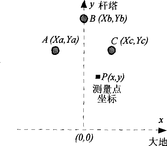
[0125] 1) Determine the location of the magnetic field detection point according to the actual line structure parameters,

[0126] 2) Install a magnetic field sensor on the wall near the wall bushing of the overhead outgoing line that cannot obtai...

Embodiment 3

[0134] 3. Use traveling wave information mainly based on zero-mode components to realize traveling wave distance measurement for small current grounding faults, and use traveling wave information mainly based on line mode components to realize traveling wave distance measurement for short-circuit and small current ground faults

[0135] 1) Install electric field sensors and (or) magnetic field sensors near the two ends of the line to detect space electric fields and (or) magnetic fields to obtain fault voltage and (or) current traveling wave signals mainly based on zero-mode components or line-mode components, as shown in the attached Figure 10 as shown,

[0136] 2) The distance measuring devices at both ends of the line record the fault traveling wave information obtained by the electromagnetic field sensor and transmit the data to the PC workstation of the control center,

[0137] 3) Utilizing the recorded time when the initial traveling wave of the fault mainly with zero-m...


PUM


Abstract

The invention relates to a method for obtaining failure information of a power system, which uses space electromagnetic field induction to obtain the failure information of an overhead line, wherein failure voltage traveling wave and failure transient state and steady voltage information are obtained through measuring an electric field on the lower portion of the overhead line, failure current traveling wave and failure transient state and steady current information are obtained through measuring a magnetic field, and the failure voltage traveling wave, the transient state and the steady information of the overhead line are obtained through inducing space electric field by using a capacitive electric field sensor. For a small current grounding system, failure direction is calculated through using components of the transient state failure information which is obtained through using the electromagnetic field induction in a characteristic frequency band, and the failure distance is calculated through the failure voltage and the current traveling wave information which are obtained by the electromagnetic field induction for output circuits and distribution lines. The method for obtaining failure information of a power system has the advantages that the failure traveling wave information, the transient state and steady failure voltage and current information are easily obtained, the safety is greatly increased, and the cost is reduced and the like.

Description

technical field [0001] The invention relates to a method for acquiring fault information of power transmission and power distribution overhead lines in a power system. [0002] The invention particularly relates to a method for acquiring fault traveling wave information, fault transient state information and fault steady state information by using space electromagnetic field induction. Background technique [0003] my country's medium-voltage power distribution system widely adopts the neutral point non-effectively grounded (not grounded or grounded through the arc suppression coil) operation mode, which is called a small current grounding system. Most of the single-phase ground fault detection devices applied to small current grounding systems are realized by detecting the zero-sequence current and zero-sequence voltage of the system. At present, the method of extracting zero-sequence current commonly used in power systems is to install a zero-sequence current transformer ...

Claims


Application Information

Patent Timeline
IPC IPC(8): H02H7/26H02H9/08G01R31/08
Inventor 薛永端徐丙垠孙波王涛
Owner SHANDONG KEHUI POWER AUTOMATION
Why Eureka
Try Eureka