
Laser cutting method of amorphous alloy strip steel rolled stock

An amorphous alloy, laser cutting technology, used in laser welding equipment, welding/cutting auxiliary equipment, metal processing equipment, etc., can solve the problems of strip damage, inability to process strip, affecting processing accuracy, etc., to achieve guaranteed results and accuracy, suitable for promotion and use, and ensure the effect of machining accuracy

Inactive Publication Date: 2009-06-24
包头高源激光科技发展有限公司
View PDF0 Cites 15 Cited by
  • Summary
  • Abstract
  • Description
  • Claims
  • Application Information

AI Technical Summary

Problems solved by technology

[0006] 2. The precision of the shearing equipment is very high, if there is a large "offset", it will be "brittle";
[0007] 3 There are requirements for the width of the strip, and the strip with a width of less than 5mm cannot be processed;
[0008] 4. Mechanical shearing belongs to "contact" processing. When it is rolled to passivation, "burrs" will appear on the edge of the sheared strip. In some manufacturing fields that require high strip shape, this kind of strip will not be available;
[0009] 5. The shearing efficiency is low and the processing cost is high
[0016] However, if the existing laser cutting technology is used to cut the amorphous alloy strip, due to the ultra-thin thickness of the amorphous alloy strip, if it is not fixed during cutting, it will easily produce "drift", which will affect To the processing accuracy, but if it is fixed by conventional mechanical methods, it will affect the processing efficiency and cause damage to the strip itself

Method used


Image

  • Laser cutting method of amorphous alloy strip steel rolled stock
  • Laser cutting method of amorphous alloy strip steel rolled stock

Examples


Embodiment 1

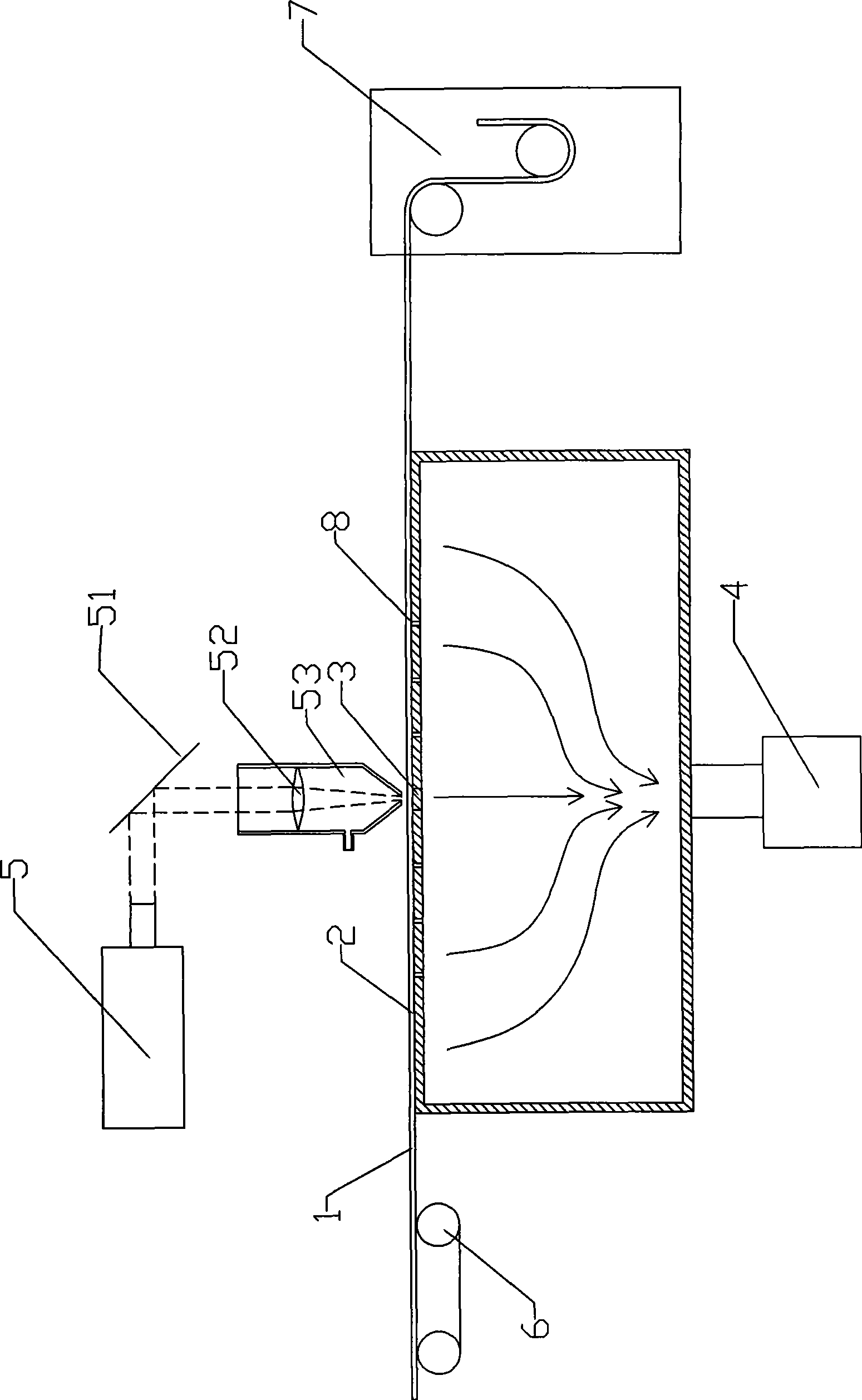
[0051] The amorphous alloy strip with a thickness of 0.03mm passes through the processing channel at a constant speed, the vacuum device is a vacuum pump, the ultimate vacuum can be obtained at 0.01Pa, and the pulse energy density is 1×10 5 w / cm 2 , The laser beam with a pulse width of 125ms cuts the amorphous alloy strip that is close to the working surface. The surface of the alloy strip obtained by cutting is smooth, the incision is uniform and burr-free, and all index parameters meet the requirements.

Embodiment 2

[0053] The amorphous alloy strip with a thickness of 0.05mm passes through the processing position at a constant speed. The vacuum device is a vacuum pump, and the ultimate vacuum can be obtained at 0.05Pa. The pulse energy density is 1×10 6 w / cm 2 , The laser beam with a pulse width of 200ms cuts the amorphous alloy strip that is close to the working surface. The surface of the alloy strip obtained by cutting is smooth, the incision is uniform and burr-free, and all index parameters meet the requirements.

Embodiment 3

[0055] The amorphous alloy strip with a thickness of 0.1mm passes through the processing position at a constant speed, the vacuum device is a vacuum pump, the ultimate vacuum can be obtained at 0.1Pa, and the pulse energy density is 1×10 8 w / cm 2 , The laser beam with a pulse width of 250ms cuts the amorphous alloy strip that is close to the working surface. The surface of the alloy strip obtained by cutting is smooth, the incision is uniform and burr-free, and all index parameters meet the requirements.


PUM

PropertyMeasurementUnit
Pulse widthaaaaaaaaaa
Thicknessaaaaaaaaaa
Thicknessaaaaaaaaaa

Abstract

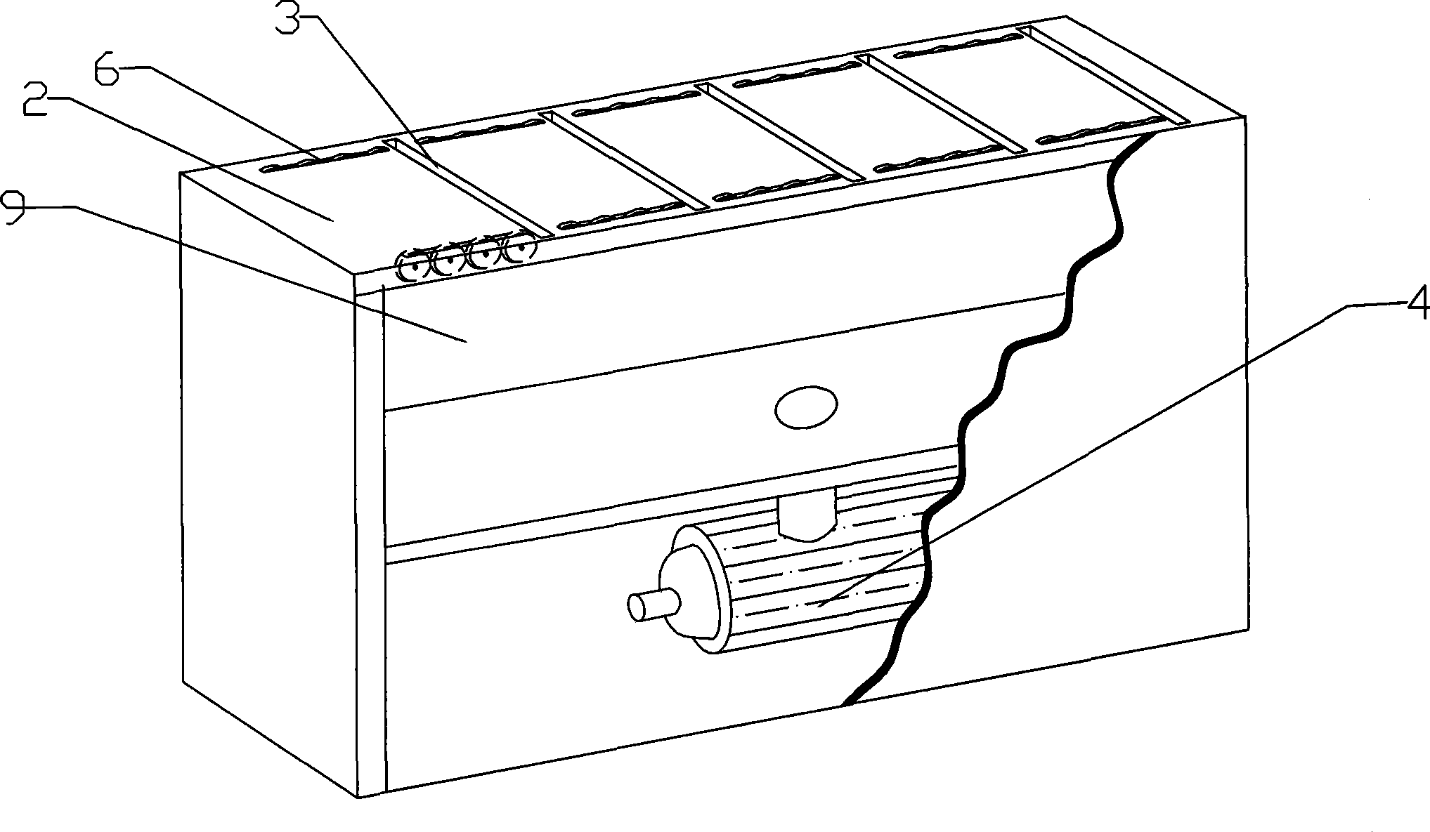
The invention discloses a laser cutting method for an amorphous alloy strip material. The amorphous alloy strip material positioned in a machining passage is fixed through a suction pore canal connected with a vacuum extractor; therefore, the method ensures that the amorphous alloy strip material can cling to the machining passage under the action of air pressure generated by the vacuum extractor and does not have dithering in the horizontal or vertical direction; furthermore, a laser is used to cut the amorphous alloy strip material positioned on a machining position. The method solves the difficult problem that the amorphous alloy strip material is easy to shift in the laser cutting process, ensures machining precision, has simple operation and reliable effect and is suitable for popularization and use.

Description

technical field [0001] The invention relates to the field of laser cutting, in particular to a laser cutting method for an amorphous alloy strip. Background technique [0002] It is reported in the prior art literature that after the metal is melted, the internal atoms are in an active state. Once the metal starts to cool, the atoms will gradually arrange in an orderly manner according to a certain crystal state as the temperature drops, forming a crystal. If the cooling process is rapid, the atoms freeze before they can rearrange, resulting in an amorphous alloy. Therefore, people use rapid solidification technology to prepare amorphous alloys. The high-temperature molten steel in the molten state is sprayed onto the high-speed rotating cooling roller, and the molten steel is rapidly cooled at a speed of one million degrees per second, and it takes only one thousandth of a second to reduce the molten steel at 1300°C to below 200°C. Amorphous ribbons are formed. [0003]...

Claims


Application Information

Patent Timeline
IPC IPC(8): B23K26/38B23K37/04
Inventor 高勇
Owner 包头高源激光科技发展有限公司
Learn More