Temperature fuse and method of manufacturing the same

A technology for thermal fuses and manufacturing methods, which is applied in fuse manufacturing, emergency protection devices, electrical components, etc., can solve the problems of high cost and large investment, and achieve the effects of good airtightness, thin product size, and stable fusing performance

Inactive Publication Date: 2009-06-24
SHANGHAI CHANGYUAN WAYON CIRCUIT PROTECTION CO LTD
View PDF2 Cites 9 Cited by
  • Summary
  • Abstract
  • Description
  • Claims
  • Application Information

AI Technical Summary

Problems solved by technology

A kind of thin thermal fuse packaged in plastic film came into being, but the m

Method used


Image

  • Temperature fuse and method of manufacturing the same
  • Temperature fuse and method of manufacturing the same
  • Temperature fuse and method of manufacturing the same

Examples


Embodiment 1

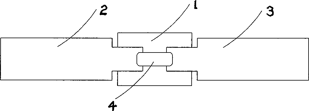
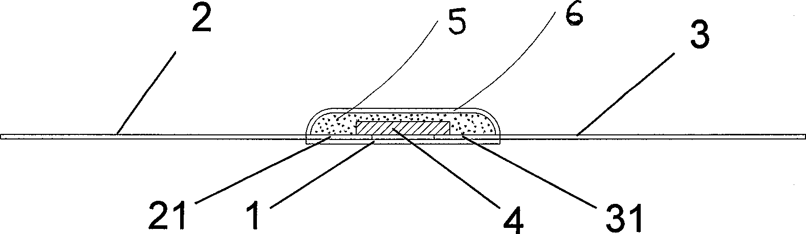
[0040] see figure 1 It is a schematic diagram of the partial composition structure of the thermal fuse of embodiment 1 and figure 2 As shown in the schematic diagram of the front view structure of the thermal fuse in Embodiment 1, a method for manufacturing a thermal fuse includes the following steps:

[0041] Stamping 0.1mm thick PBT film material into 4.5×3.2mm rectangular negative film 1;

[0042] Bond a pair of nickel metal electrodes 2 and 3 with a width of 1.4mm and a pair of 2.5×10mm on the top of the negative film 1. The nickel metal electrodes 2 and 3 are relatively arranged in a straight line and leave a distance of 0.5mm between the ends 21 and 31;

[0043] A 0.8×2mm fusible alloy 4 is welded between the two nickel metal electrodes 2 and 3 by heat welding;

[0044] Coating the flux 5 on the surface of the fusible alloy 4 by heating and dropping, covering the fusible alloy 4, and heating slightly to make the fusible alloy 4 flow and form naturally;

[0045] Add a...

Embodiment 2

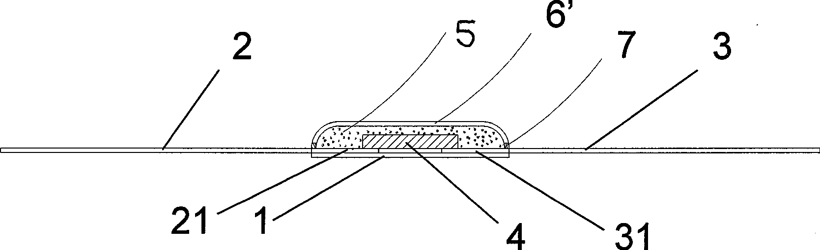
[0049] see image 3 As shown in the schematic diagram of the front view of the thermal fuse in Example 2, the 0.1mm thick PBT film material is stamped into a 4.5×3.2mm rectangular negative sheet 1;

[0050] Bond a pair of nickel metal electrodes 2 and 3 with a width of 1.4mm and a pair of 2.5×10mm on the top of the negative film 1. The nickel metal electrodes 2 and 3 are relatively arranged in a straight line and leave a distance of 0.5mm between the ends 21 and 31;

[0051] A 0.8×2mm fusible alloy 4 is welded between the two nickel metal electrodes 2 and 3 by heat welding;

[0052] Coating the flux 5 on the surface of the fusible alloy 4 by heating and dropping, covering the fusible alloy 4, and heating slightly to make the fusible alloy 4 flow and form naturally;

[0053] Add room temperature curing adhesive or light curing adhesive 6' dropwise above the flux 5 and allow it to flow naturally;

[0054] A ring-shaped upper cover sheet 7 is placed, and the upper cover sheet 7...


PUM


Abstract

The invention relates to a thermal fuse for electronic circuit protection, in particular to a thermal fuse for lithium-ion battery protection, and a manufacturing method thereof. The thermal fuse comprises a plastic backing film; a pair of metal electrodes are arranged above the backing film; the metal electrodes are relatively linearly arranged and are provided with space among the end parts; the metal electrodes are welded through fusible alloy; wherein, the surface of the fusible alloy is covered with cosolvent which is coated by a layer of adhesive; the adhesive and the backing film form a closed space; the end parts of the metal electrodes, the fusible alloy and the cosolvent are sealed in the closed space; or, the surface of the fusible alloy is covered with cosolvent, and the backing film at the external side of the cosolvent is provided with an annular upper cover piece; the cosolvent is coated with a layer of adhesive; the adhesive, the upper cover piece and the backing film form a closed space; and the end parts of the metal electrodes, the fusible alloy and the cosolvent are sealed in the closed space.

Description

technical field [0001] The invention relates to a thermal fuse for electronic circuit protection, in particular to a thermal fuse for lithium battery protection and a manufacturing method thereof. Background technique [0002] Lithium-ion batteries are currently widely used in small handheld devices such as mobile phones, digital cameras, digital cameras, MP3, MP4, game consoles, etc. However, due to the inherent characteristics of lithium-ion batteries, once the lithium-ion battery is overcharged and exceeds 4.35V, lithium ions will form dendrite metal on the surface of the carbon negative electrode, and may pierce the separator, resulting in an internal short circuit between the positive and negative electrodes, thereby promoting The battery temperature rises rapidly, and because lithium-ion batteries are different from NiCd batteries and NiH batteries, the electrolyte is also a flammable substance, so the energy of the explosion is very large. As the requirements for long...

Claims


Application Information

Patent Timeline
IPC IPC(8): H01H85/05H01H85/055H01H69/02
Inventor 钱朝勇张子川沈十林
Owner SHANGHAI CHANGYUAN WAYON CIRCUIT PROTECTION CO LTD
Why Eureka
Try Eureka