
Method for manufacturing semiconductor device

A manufacturing method and semiconductor technology, applied in semiconductor/solid-state device manufacturing, semiconductor devices, electrical components, etc., can solve problems such as inability to apply strain technology and inability to realize channel regions

Inactive Publication Date: 2009-07-01
SEIKO EPSON CORP
View PDF0 Cites 0 Cited by
  • Summary
  • Abstract
  • Description
  • Claims
  • Application Information

AI Technical Summary

Problems solved by technology

Therefore, regarding the SBSI method, conventional strain technologies such as SGOI and SSOI cannot be applied, and an SBSI device (ie, an SOI device formed by the SBSI method) in which the channel region is strained to improve electron mobility cannot be realized.

Method used


Image

  • Method for manufacturing semiconductor device
  • Method for manufacturing semiconductor device
  • Method for manufacturing semiconductor device

Examples


Embodiment Construction

[0040] Hereinafter, embodiments of the present invention will be described with reference to the drawings.

[0041] (1) About the manufacturing process

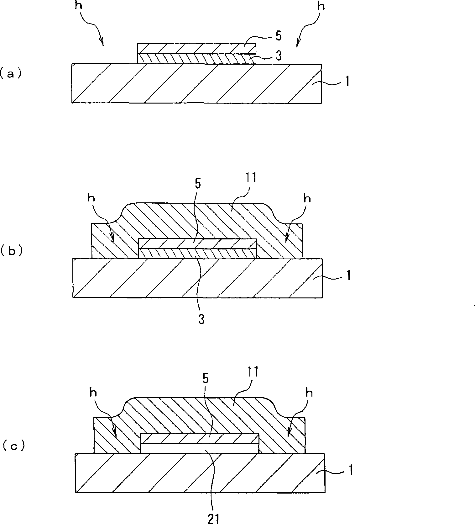
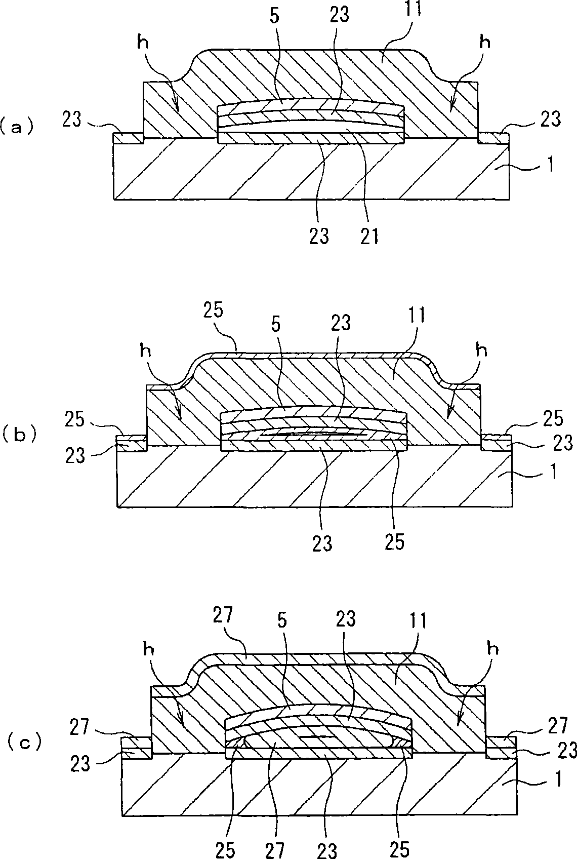
[0042] figure 1 (a)~ figure 2 (c) is a cross-sectional view illustrating a method of manufacturing a semiconductor device according to an embodiment of the present invention.

[0043] First, in figure 1 In (a), a germanium silicide (SiGe) layer 3 is formed on a bulk silicon (Si) substrate 1, and a single crystal silicon (Si) layer 5 is formed thereon. These SiGe layer 3 and Si layer 5 are continuously formed by, for example, an epitaxial growth method. Next, the Si layer 5 and the SiGe layer 3 are partially etched respectively by photolithography technology and etching technology. As a result, the support hole h having the Si substrate 1 as the bottom surface is formed in a region overlapping with the element isolation region (that is, the region where the SOI structure is not formed) in plan view. In this etching st...


PUM


Abstract

The invention provides a method for manufacturing a semiconductor device capable of implementing SBSI element that improves mobility of electronics, comprising: a process of forming an SiGe layer on an Si substrate (1), a process of forming an Si layer (5) on the SiGe layer, a process of etching the Si layer (5) and SiGe layer to form a bearer hole (h) that runs through the Si layer (5) and SiGe layer; a process of forming a bearer (11) on the bearer hole (h); a process of etching the Si layer (5) to form grooves ( front and rear sides of a paper) that exposes the SiGe layer; a process of etching the SiGe layer via the grooves to form a cavity (21) between the Si layer (5) and Si substrate (1); a process of forming an a-Si film (25) within the cavity (21); and a process of thermally oxidizing the a-Si film (25) to form an SiO2 film (27).

Description

technical field [0001] The present invention relates to a method of manufacturing a semiconductor device, and more particularly to a technique for partially forming a so-called SOI (Silicon On Insulator) structure on a semiconductor substrate. Background technique [0002] With regard to field effect transistors formed on SOI substrates, attention has been paid to their usefulness in terms of ease of element isolation, no lock-up, and small source / drain junction capacitance. In particular, fully depleted SOI transistors have low power consumption, can operate at high speed, and are easy to drive at low voltages. Therefore, researches on making SOI transistors operate in fully depleted mode are active. As the SOI substrate, for example, a SIMOX (Separation by Implanted Oxygen) substrate or a bonded substrate can be used, and their manufacturing methods are relatively special and cannot be manufactured by a common CMOS process. [0003] For this purpose, there is known the SB...

Claims


Application Information

Patent Timeline
Patent Type & Authority Applications(China)
IPC IPC(8): H01L21/20H01L21/335H01L21/762H01L21/84
CPCH01L29/1054H01L29/66651H01L29/7846H01L21/76251H01L21/20
Inventor 松泽勇介
Owner SEIKO EPSON CORP
Learn More