Method for gas-phase growth of carbon fibre

A technology of vapor phase growth and carbon fiber, which is applied to the chemical characteristics of fibers, textiles and papermaking, etc., can solve the problems such as the difficulty in optimizing the ratio of catalysts to hydrocarbons, the existence of catalyst particles in nanoscale form, and the uneven distribution of iron particles, etc., to achieve improved Oriented reactivity, easy vapor phase growth of carbon fibers, and reduced activation energy

Inactive Publication Date: 2009-07-08
SHENZHEN UNIV
View PDF0 Cites 10 Cited by
  • Summary
  • Abstract
  • Description
  • Claims
  • Application Information

AI Technical Summary

Problems solved by technology

Although this method provides the possibility of preparing a large number of vapor-grown carbon fibers, it is difficult to optimize the ratio of catalyst to hydrocarbon gas compound, the distribution of iron particles is not uniform during the spraying process, and the sprayed catalyst particles are difficult to exist in nanoscale form, and the preparation Vapor-grown carbon fibers are always accompanied by a large amount of carbon black

Method used


Image

  • Method for gas-phase growth of carbon fibre
  • Method for gas-phase growth of carbon fibre
  • Method for gas-phase growth of carbon fibre

Examples


Embodiment 1

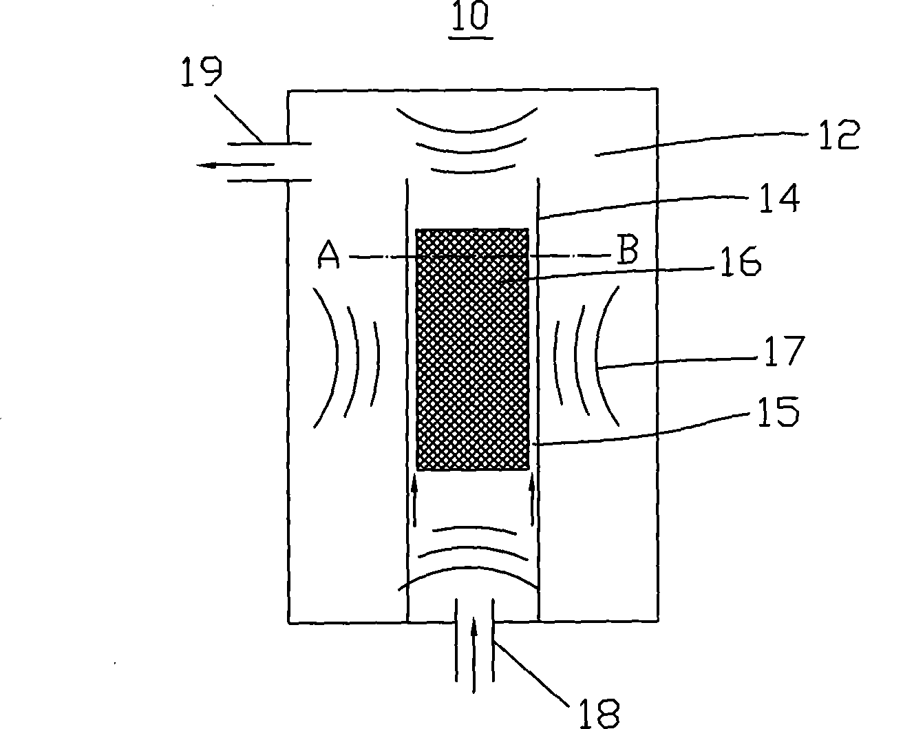
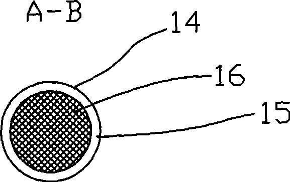
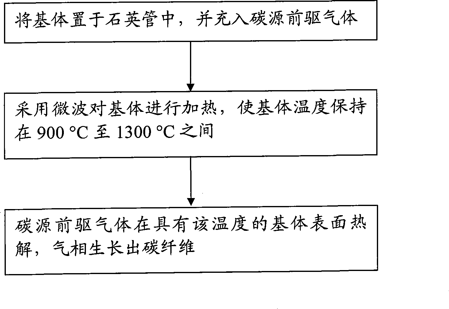
[0028] like figure 1 As shown, the substrate 16 is placed in the quartz tube 14 first, and the gap 15 between the substrate 16 and the quartz tube 14 is filled with carbon source precursor gas. In this embodiment, a substrate made of alumina is used, methane gas is the carbon source precursor gas, nitrogen gas is the carrier gas and diluent, and their mixed gas is passed through the inlet 18, and the residence time of the gas is 0.5s. The microwave source forms the microwave 17 to heat the substrate 16, and the heating reaches the pyrolysis temperature of the precursor, that is, methane gas. The temperature is maintained at 1300°C. After 1 hour of pyrolysis deposition, carbon fibers can be produced, as Figure 4 As shown, the carbon fibers are in the form of an array.

Embodiment 2

[0030] like figure 1 As shown, the substrate 16 is placed in the quartz tube 14 first, and the gap 15 between the substrate 16 and the quartz tube 14 is filled with carbon source precursor gas. In this embodiment, a substrate made of alumina is used, propylene gas is used as the carbon source precursor, nitrogen is used as the carrier gas and diluent, and their mixed gas is introduced from the inlet, and the residence time of the gas is 0.3s. The substrate is heated by a microwave source until it reaches the pyrolysis temperature of the precursor, and the temperature is maintained at 1100°C. After 1 hour of pyrolysis deposition, the following Figure 4 Carbon fiber shown.

Embodiment 3

[0032] like figure 1 As shown, the substrate 16 is placed in the quartz tube 14 first, and the gap 15 between the substrate 16 and the quartz tube 14 is filled with carbon source precursor gas. In this embodiment, a substrate made of alumina is used, acetylene gas is used as the carbon source precursor, nitrogen is used as the carrier gas and diluent, and their mixed gas is introduced from the inlet, and the residence time of the gas is 0.1s. The substrate is heated by a microwave source until it reaches the pyrolysis temperature of the precursor, and the temperature is maintained at 900°C. After 1 hour of pyrolysis deposition, the following Figure 4 Carbon fiber shown.


PUM


Abstract

The invention provides a method for preparing vapor-grown carbon fiber which includes steps as follows: placing a matrix into a reacting chamber and filling with carbon source precursor gas; heating the matrix using microwave for making the matrix temperature in 900 to 1300 DEG. C; the carbon source precursor gas pyrolyzing on the matrix surface with the temperature for growing carbon fibre. The method uses microwave for heating, gets help from polar material acted by microwave, has characteristics of self heating and rapid heating speed, activation of non-heat effect of microwave to material reaction and inductivity of process change, reduces activation energy, changes reaction dynamics, accordingly promotes reaction selectly, and improves direction reaction activation, is easy to grow vapor-grown carbon fibre on the matrix surface.

Description

technical field [0001] The invention relates to a method for preparing carbon materials, in particular to a method for vapor phase growth of carbon fibers. Background technique [0002] At present, there are two main methods for vapor phase growth of carbon fibers: matrix method and spray method or flow catalyst method. The so-called matrix method is to use graphite or ceramics as the matrix, apply catalyst particles as "seeds", pass hydrocarbon gas compounds at high temperature, and at the same time mix hydrogen gas, and then decompose the hydrocarbon gas under the action of the catalyst. Fibrous carbon was deposited on one side of the particles. Rodrigue sprays ultra-fine catalyst powder on the substrate, and degrades hydrocarbon gas at high temperature to prepare vapor-phase grown carbon fibers of 50nm to 80nm. This matrix catalyst method can prepare high-quality vapor-grown carbon fibers. However, the preparation of ultra-fine catalyst particles is very difficult, and...

Claims


Application Information

Patent Timeline
Patent Type & Authority Applications(China)
IPC IPC(8): D01F9/127
Inventor 曾燮榕邹继兆黎晓华邓飞符冬菊
Owner SHENZHEN UNIV
Why Eureka
Try Eureka