Biomass gas and exhaust heat combination type materiel drying system

A drying system and biomass technology, applied in drying, dryer, heat exchanger types and other directions, can solve problems such as unfavorable energy saving and emission reduction, large energy consumption, etc., achieving simple structure, convenient manufacturing, and saving production costs Effect

Inactive Publication Date: 2009-07-15
NANJING UNIV
View PDF0 Cites 7 Cited by
  • Summary
  • Abstract
  • Description
  • Claims
  • Application Information

AI Technical Summary

Problems solved by technology

[0003] The purpose of this invention is to solve the problem that the current beer, alcohol, fuel ethanol and other production enterprises mainly rely on electric power and fuel oil to dry the materials in the production process, resulting in large energy consumption, which is not conducive to energy saving and emission reduction. A large amount of biomass gas generated in the process and landfill is used as heating energy, a biomass gas and waste heat composite material drying system that meets the requirements of energy saving and emission reduction

Method used


Image

  • Biomass gas and exhaust heat combination type materiel drying system

Examples


Embodiment Construction

[0016] The present invention will be further described below in conjunction with the drawings and embodiments.

[0017] Such as figure 1 Shown.

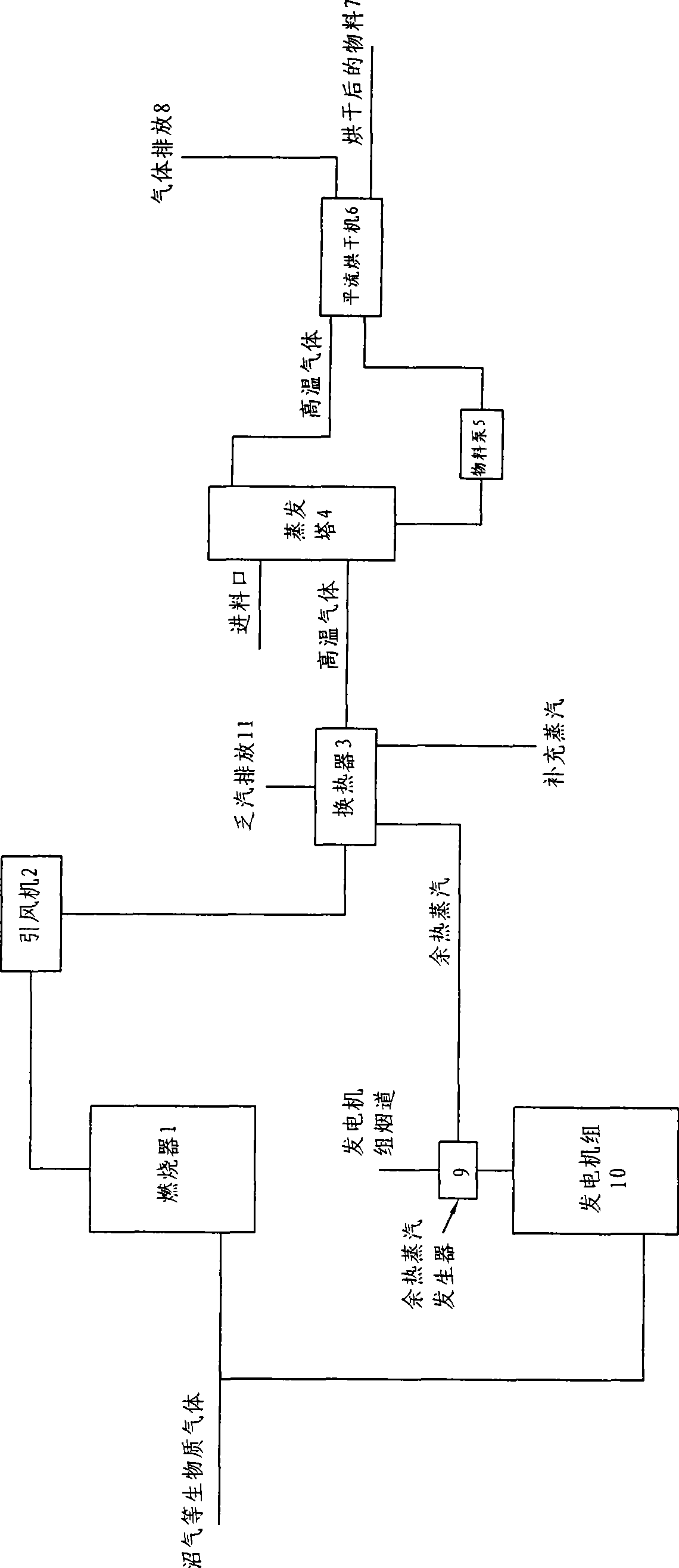
[0018] A biomass gas and waste heat composite material drying system, which includes a burner 1, an induced draft fan 2, a heat exchanger 3, an evaporation tower 4, a material pump 5 and a flat flow dryer 6, and the inlet end of the burner 1. The output of the burner 1 is connected to the suction port of the induced draft fan 2 through the pipeline, the output of the induced draft fan 2 is connected to an inlet of the heat exchanger 3, and the heat exchanger 3 also passes through the pipeline. Connected to the source of supplementary steam and / or waste heat steam, the output of the heat exchanger 3 is connected to the air inlet at the lower part of the vertical evaporation tower 4 through a pipe, and the upper part of the vertical evaporation tower 4 is provided with an inlet for the dried material. The lower part of the evaporation towe...


PUM


Abstract

The present invention provides a biomass gas and a residual-heat composite material drying mechanism. The invention is characterized in that the gas inlet end of combustor is connected with the gas source of biomass gas through a pipeline. The output of the combustor is connected with the gas suction opening of a draft fan through the pipeline. The output of the draft fan is connected with one gas inlet of a heat exchanger. The heat exchanger is also connected with a steam gas source for supplying steam and / or residual heat steam gas source through the pipeline. The output of the heat exchanger is connected with the gas inlet at the lower part of a vertical evaporator tower. The upper part of the vertical evaporator tower is installed with a dried material inlet. The lower part of the evaporator tower is provided with a material discharge opening and is connected with the material inlet end of a material pump through a conveying tube. The material discharge end of the material pump is connected with the material inlet end of a horizontal flow dryer. The upper part of evaporator tower is installed with a high temperature gas outlet opening which is led to the material inlet opening of the horizontal flow dryer or the lower part of the conveyor belt through the pipeline for further heating and drying the material in the horizontal flow dryer. The outlet end of horizontal flow dryer is connected with the subsequent material conveying device and is connected with a gas discharge tube. The biomass gas and a residual-heat composite material drying mechanism of the invention has the advantages of simple structure, easy realization, contribution to energy conservation and emission reduction and reduction of production cost.

Description

Technical field [0001] The invention relates to an energy comprehensive utilization device, in particular to a device that uses the heat generated by biomass gas to heat materials in the production process to replace traditional energy heating devices, specifically a biomass gas and waste heat composite type Material drying system. Background technique [0002] The current material drying equipment uses steam or combustible gas as a direct heat source, and most of them use electricity, coal, diesel or natural gas as fuel. This requires the consumption of a large amount of primary energy, which is not conducive to energy saving, emission reduction and sustainable development. At the same time, a large amount of biomass gas is produced every day in industries such as beer, alcohol, fuel ethanol and other industries, as well as in landfills and sewage treatment plants. These gases are either directly discharged into the atmosphere to pollute the environment or use incineration. The ...

Claims


Application Information

Patent Timeline
Patent Type & Authority Applications(China)
IPC IPC(8): F26B20/00F26B17/14F26B15/18F26B15/10F26B21/00F28D7/00
Inventor 陈泽智龚惠娟吴未立程洋姜茹王慧
Owner NANJING UNIV
Why Eureka
Try Eureka