Methods and apparatus for beam density measurement in two dimensions

A beam density and measurement technology, applied in the field of two-dimensional beam density measurement, can solve the problem of not being large enough

Active Publication Date: 2009-07-15
VARIAN SEMICON EQUIP ASSOC INC
View PDF0 Cites 5 Cited by
  • Summary
  • Abstract
  • Description
  • Claims
  • Application Information

AI Technical Summary

Problems solved by technology

The associated opening in the processing chamber may not be large enough to allow a large number of pixels and associated wiring to be coupled to the profilometer sensor

Method used


Image

  • Methods and apparatus for beam density measurement in two dimensions
  • Methods and apparatus for beam density measurement in two dimensions
  • Methods and apparatus for beam density measurement in two dimensions

Examples


Embodiment Construction

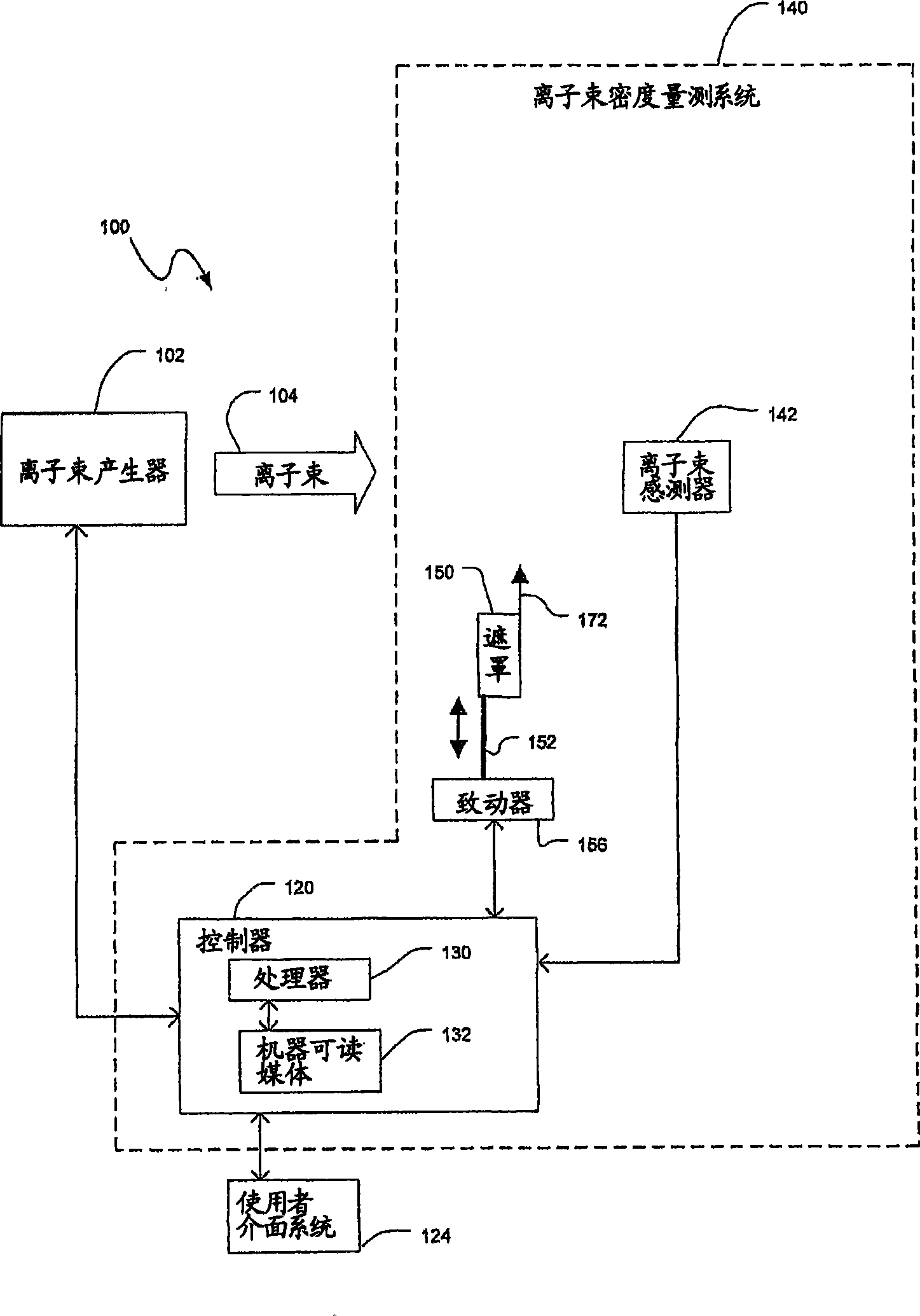
[0090] Figure 1A A block diagram of an apparatus 100 including an ion beam generator 102 and an ion beam density measurement system 140 consistent with an embodiment of the invention is illustrated. The ion beam generator 102 may include various types of components and systems to generate a beam 104 . Beams may include, but are not limited to, ion beams, light beams, electron beams, and neutral particle beams.

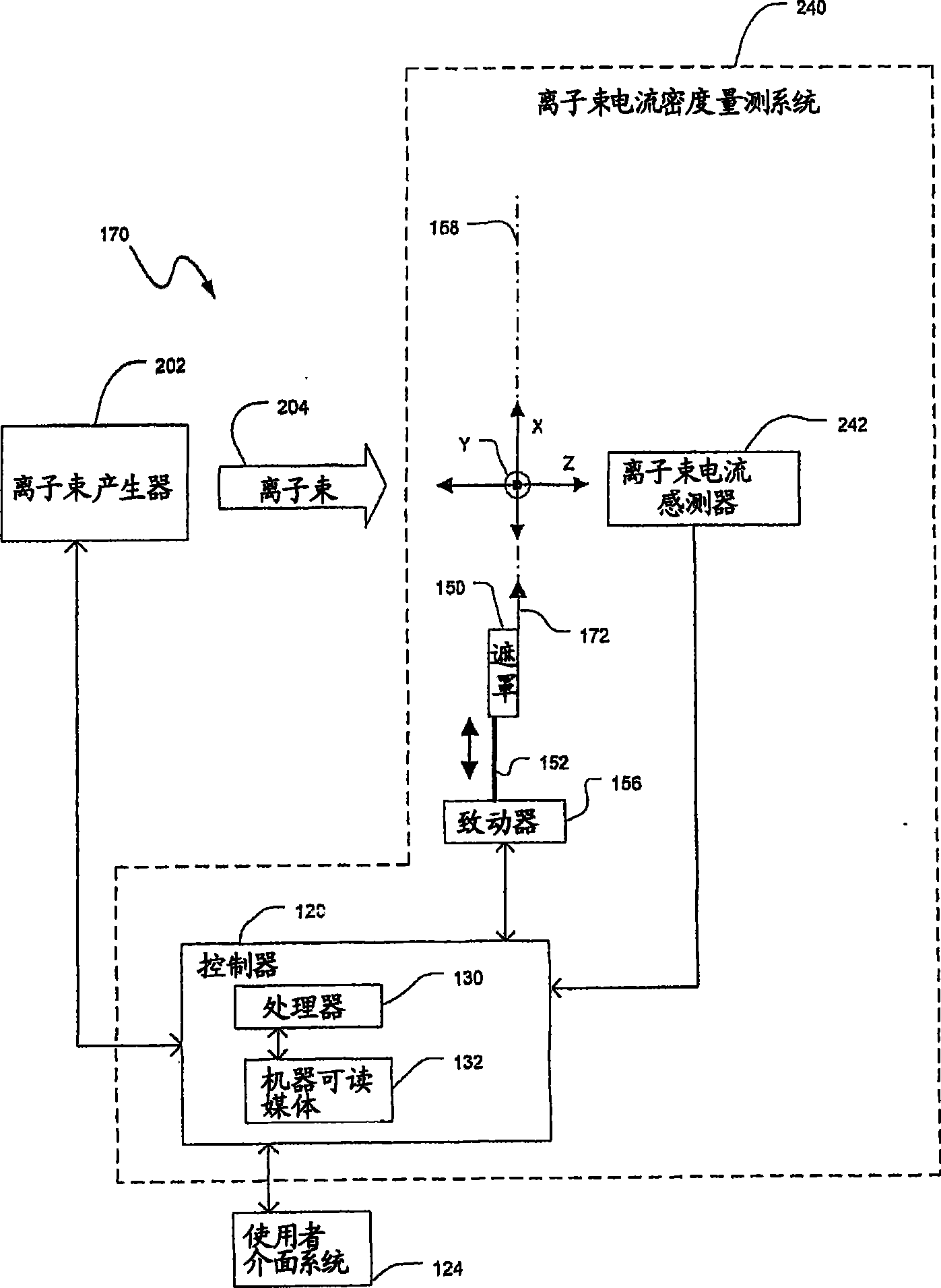
[0091] The ion beam density measurement system 140 may include a shield 150 , an actuator 156 , an ion beam sensor 142 and a controller 120 . The mask 150 can be fabricated from a variety of materials to selectively block the beam 104 . Actuator 156 may include one or more motors, drive mechanisms, mechanical linkages, and any other components as known in the art. Actuator 156 may translate mask 150 relative to ion beam sensor 142 by translating mask 150, ion beam sensor 142, or some combination of the two. In an embodiment, the actuator 156 may translate the mask ...


PUM


Abstract

A beam density measurement system includes a shield, a beam sensor, and an actuator. The beam sensor is positioned downstream from the shield in a direction of travel of a beam. The beam sensor is configured to sense an intensity of the beam, and the beam sensor has a long dimension and a short dimension. The actuator translates the shield relative to the beam sensor, wherein the shield blocks at least a portion of the beam from the beam sensor as the shield is translated relative to the beam sensor, and wherein measured values of the intensity associated with changes in a position of the shield relative to the beam sensor are representative of a beam density distribution of the beam in a first direction defined by the long dimension of the beam sensor.

Description

technical field [0001] The invention relates to a method and a device for measuring two-dimensional beam density. Background technique [0002] Ion implantation is a standard technique for introducing property-altering impurities into various substrates. The desired impurity material is ionized in the ion source, the ions are accelerated to form an ion beam with a specified energy and directed at the front surface of the substrate. A common example is the change in conductivity of semiconductor materials via implantation of impurities such as boron, arsenic, etc. The energetic ions in the ion beam penetrate into the bulk of the semiconductor material and intercalate into the crystal lattice of the semiconductor material to form regions of desired conductivity. [0003] Ion implanters generally include an ion source for converting a gas or solid material into an ionized plasma, from which a well-defined ion beam is extracted through the use of well-established ion beam extr...

Claims


Application Information

Patent Timeline
Patent Type & Authority Applications(China)
IPC IPC(8): H01J37/304H01J37/244H01J37/317
CPCH01J2237/24507G01J1/04H01J37/3171G01J1/4257G01J2001/4261H01J2237/30472H01J2237/24542H01J2237/31703H01J37/244G01J1/0437H01J2237/2446G01J1/0448H01J2237/24578H01L21/265H01L22/00H01J37/304H01J37/317
Inventor 阿塔尔·古普塔约瑟·C·欧尔森葛桔·A·洛里斯
Owner VARIAN SEMICON EQUIP ASSOC INC
Why Eureka
Try Eureka