Formaldehyde absorbing tower

A formaldehyde absorption tower and formaldehyde gas technology, applied in the field of formaldehyde, can solve the problems of excess formaldehyde residue, impact on efficiency, high price, etc., and achieve the effect of recovering heat energy, reducing equipment investment, and reducing cooling water costs

Inactive Publication Date: 2012-04-18
南通华鑫传质设备科技有限公司
View PDF0 Cites 0 Cited by
  • Summary
  • Abstract
  • Description
  • Claims
  • Application Information

AI Technical Summary

Problems solved by technology

Therefore, the absorption driving force is not high, and the tail gas from the top of the tower is not well controlled, which can easily cause the residual formaldehyde to exceed the standard. First, it will affect the environment and second, it will affect the benefit
[0007] (2) The formaldehyde aqueous solution discharged from the bottom of the formaldehyde absorption tower, the heat is not recycled, but cooled with a large amount of cooling water, increasing the load of the cooling water cooling tower
Especially in summer and when the plate cooler is scaled due to circulating water, it is difficult to cool the formaldehyde solution in the plate cooler, and part of the high-temperature formaldehyde solution in the plate cooler returns to the formaldehyde absorption tower for circulation and absorption, which is even more difficult to ensure absorption effect, creating a vicious circle
[0008] (3) The formaldehyde absorption tower and plate cooler are made of stainless steel, which is expensive
[0009] (4) The circulating cooling water used by the plate heat exchanger is very easy to deposit mud and scale, which is quite troublesome to deal with and seriously affects the normal production. It must be parked and cleaned one by one, consuming a lot of manpower and costs.

Method used


Image

  • Formaldehyde absorbing tower
  • Formaldehyde absorbing tower

Examples


Embodiment Construction

[0024] The present invention will be further described below in conjunction with accompanying drawing and specific embodiment:

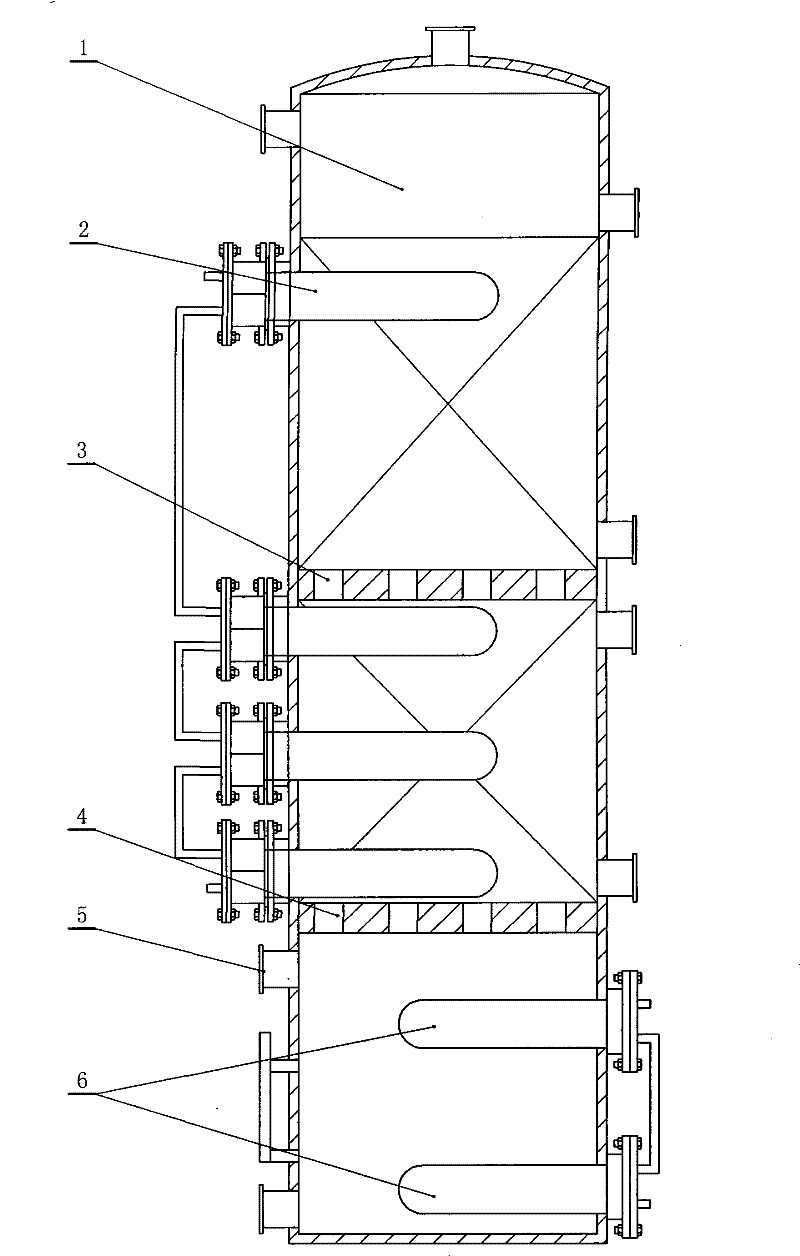
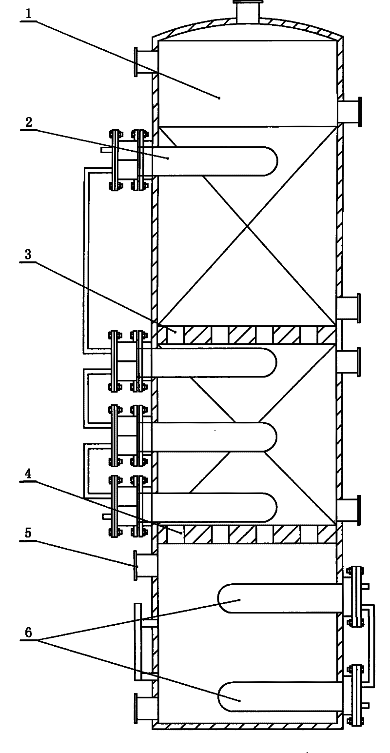
[0025] A formaldehyde absorption tower, such as figure 1 As shown, it includes the water tank packing tower, the lower part of the water tank packing tower has a hot formaldehyde gas inlet, a layer of lower grid plate is installed on the inner wall of the water tank packing tower cavity above the hot formaldehyde gas inlet, and the lower grid in the water tank packing tower cavity Filling is placed on the plate, and a soft water tank is installed in the filling above the lower grid plate. The soft water tank is installed on the inner wall of the water tank packing tower cavity, and a cooling water tank is installed on the inner wall of the water tank packing tower cavity below the lower grid plate; In this embodiment, a layer of upper grid plate is installed on the inner wall of the cavity of the water tank packing tower above the lower grid plate, f...


PUM


Abstract

The invention relates to a formaldehyde absorption tower which simplifies the process of converting hot formaldehyde gas into formaldehyde finished products. The formaldehyde absorption tower consists of a water tank packed column, the lower part of which is provided with a hot formaldehyde gas inlet; the inside wall of the hollow cavity of the water tank packed column over the hot formaldehyde gas inlet is provided with a layer of lower grid plate and a filler is put on the lower grid plate in the hollow cavity of the water tank packed column; the filler over the lower grid plate is providedwith a soft water tank; the soft water tank is positioned on the inside wall of the hollow cavity of the water tank packed column and the inside wall of the hollow cavity of the water tank packed column below the lower grid plate is provided with a cooling water tank; the inside wall of the hollow cavity of the water tank packed column over the lower grid plate is provided with a layer of upper grid plate and a filler is put on the upper grid plate in the hollow cavity of the water tank packed column; the filler on the upper grid plate is provided with a soft water tank, the soft water tank is positioned on the inside wall of the hollow cavity of the water tank packed column, the soft water tank over the upper grid plate and the soft water tank over the lower grid plate are communicated; and the cooling water tank and the soft water tanks are made of aluminum.

Description

technical field [0001] The invention relates to formaldehyde, in particular to a formaldehyde absorption tower. Background technique [0002] The production of formaldehyde is based on methanol as the raw material. The methanol is evaporated and gasified in the evaporator, and then water vapor and air are introduced into the ternary gas, which enters the formaldehyde reactor and is oxidized to formaldehyde under the condition of silver (or iron molybdenum) as the catalyst. . The purpose of introducing water vapor is to make methanol react with oxygen beyond its explosive limit, so as to ensure the safety of production. [0003] 1. Presentation of the question: [0004] The traditional formaldehyde production process is to exit the hot formaldehyde gas from the silver catalyst layer. After quenching the temperature and recovering part of the heat, the hot formaldehyde gas with a temperature of 80-100 ° C enters the formaldehyde absorption from the hot formaldehyde gas inlet...

Claims


Application Information

Patent Timeline
Patent Type & Authority Patents(China)
IPC IPC(8): C07C47/058C07C45/80B01D53/18
Inventor 王承信
Owner 南通华鑫传质设备科技有限公司
Why Eureka
Try Eureka