Laser range sensor system optics adapter and method

A technology of laser distance measurement and adapter, which is applied in the direction of measuring distance, instruments, measuring devices, etc., and can solve the problems of expensive and troublesome laser probes

Inactive Publication Date: 2009-07-22
QUALITY VISION INT
View PDF3 Cites 10 Cited by
  • Summary
  • Abstract
  • Description
  • Claims
  • Application Information

AI Technical Summary

Problems solved by technology

It is expensive and cumbersome to redesign the laser probe every time the objective entrance pupil changes from the laser range sensor

Method used


Image

  • Laser range sensor system optics adapter and method
  • Laser range sensor system optics adapter and method
  • Laser range sensor system optics adapter and method

Examples


Embodiment Construction

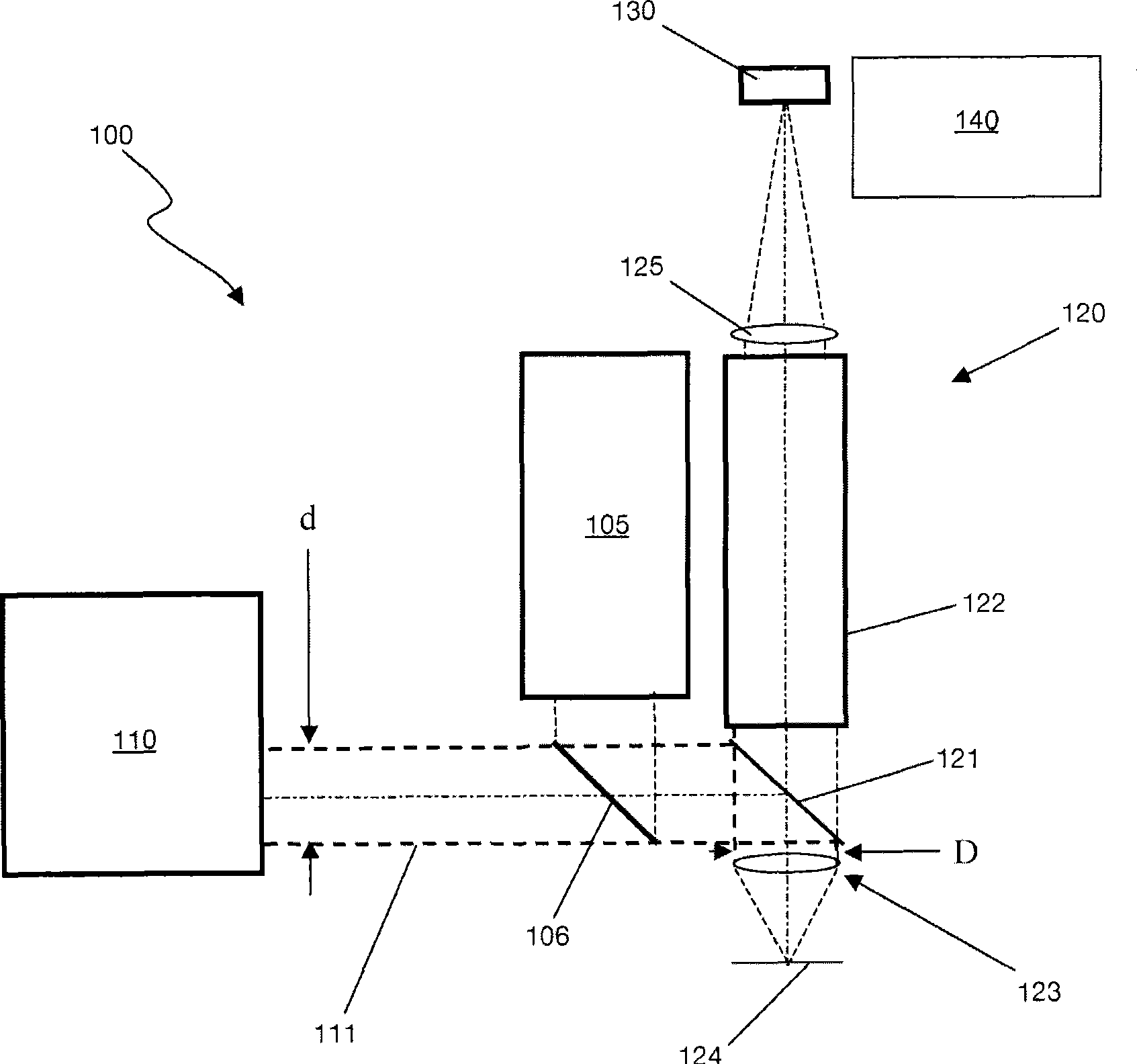
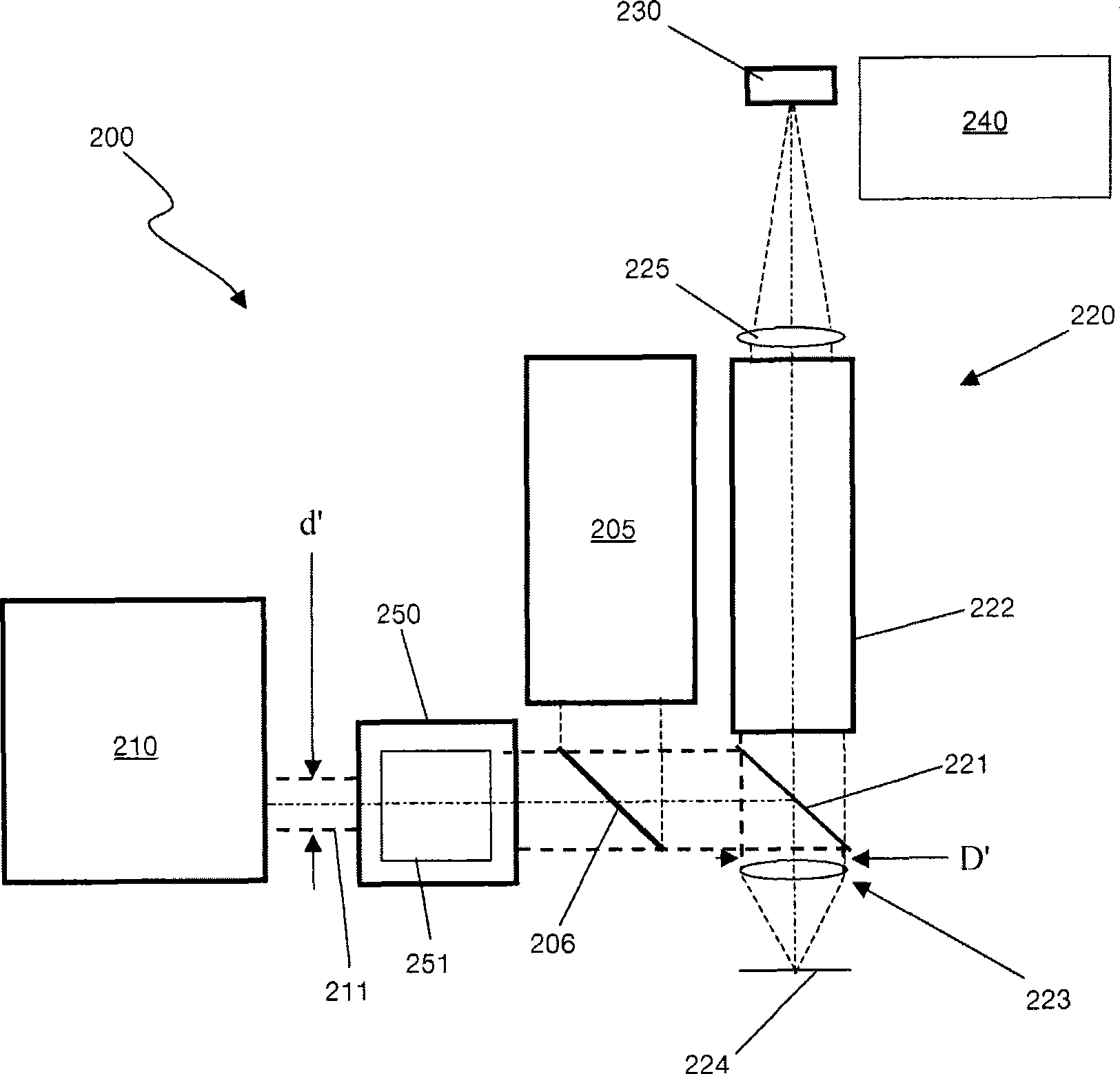
[0020] as in figure 2 As shown schematically in , the metrology system 200 may include an illumination source 205 whose radiation is directed towards an illumination beam splitter 206 or the like that redirects the radiation towards an optical system 220 . Metrology system 200 may also include a TTL laser ranging sensor probe 210 directed through illumination beam splitter 206 to optical system 220 . Such as figure 1 As in the typical system shown in , radiation from an illumination source 205 and / or a TTL probe 210 is directed to a surface to be measured 224 via a main beam splitter 221 and an objective lens 223 of an optical system 220 . The portion of the illumination light reflected and scattered from an object or surface 224 passes through beam splitter 221 and to zoom lens 222 which transmits radiation through sensor lens 225 to image sensor 230 such as a sensor of CCD camera 240 . Another portion of the reflected and scattered illumination light returns to the TTL pr...


PUM


Abstract

An adapter and a method for through the lens (TTL) laser range sensor probes enable use of a TTL probe of a given exit pupil size to be used with a shared objective lens requiring a entrance pupil size, as entered from the laser range sensor, that is different from the TTL probe exit pupil size. Embodiments of the adapter include optics, such as a first lens and a resolving second lens that expand or contract the TTL laser radiation depending on whether the first lens is a diverging, a negative focal length lens, or a converging, positive focal length lens, and the second lens is converging or diverging, respectively, in a Galilean arrangement. Embodiments also provide a Keplerian arrangement, can function with non-collimated radiation, and can include mirrors to yield a more compact adapter. Additional embodiments include at least one adjustable lens element between the first and second lenses.

Description

[0001] Cross References and Priority Claims to Related Applications [0002] This application claims priority to US Provisional Patent Application No. 60 / 746,260, filed May 2, 2006, which is hereby incorporated by reference in its entirety. technical field [0003] Embodiments relate to the field of optical metrology using video-based inspection systems and coordinate measuring machines, and multi-sensor coordinate metrology for measuring form, size and position in production and quality control. An example of such a video inspection system is described in US Patent No. 6,518,996, the disclosure of which is incorporated herein by reference. The '996 patent application discloses a video inspection apparatus comprising a compact Y-Z-X measurement axis system with imaging optics and a camera mounted on the vertical Z translation axis. This vertical imaging system can be provided with a shared objective lens above the X-Y table, with a zoom optical system behind the objective len...

Claims


Application Information

Patent Timeline
Patent Type & Authority Applications(China)
IPC IPC(8): G01C3/08
Inventor 艾力·G·积士拿大卫·B·佳麦迪·N·亚拉基
Owner QUALITY VISION INT
Why Eureka
Try Eureka