Waste water heat energy recovery system

A technology for heat energy recovery and waste water, applied in the direction of filtration circuit, indirect heat exchanger, heat exchanger type, etc., can solve the problems of filter backwashing, waste of water resources, pollution, etc., to improve heat exchange efficiency and reduce waste water Emissions and production cost reduction effects

Inactive Publication Date: 2009-07-29
仁新节能环保设备(上海)有限公司
View PDF0 Cites 6 Cited by
  • Summary
  • Abstract
  • Description
  • Claims
  • Application Information

AI Technical Summary

Problems solved by technology

Although the heat exchangers commonly used in China for waste heat recovery can produce obvious economic and environmental benefits in theory, the actual heat exchange efficiency is low and a large amount of clean water is required
For example, some systems cannot backwash the filter, and after working for a period of time, it can only be cleaned after stopping the whole system
Someone has also adopted a heat recovery device with backwashing, but this device needs to stop the entire system to realize the backwashing function, and cannot automatically perform backwashing in real time, so the filtration efficiency is low
And because this device uses clean water when backwashing, there is a problem of wasting water resources
Another problem with the existing technology is that many heat recovery systems do not use filter devices before the hot wastewater enters the heat exchanger, or use simple filters with sand and filter elements as filter materials. These filter materials need to be replaced regularly, which increases equipment maintenance. and manual operation costs, and the filtration efficiency is low. Therefore, the large particles and suspended impurities in the wastewater from the factory directly enter the heat exchanger, which makes the heat exchanger clogged, polluted and worn, and affects the operation of the heat exchanger.
In addition, none of the heat recovery systems is equipped with a heat accumulating device. Therefore, the heat cannot be displayed and accumulated online, so that it is impossible to confirm the operating status and performance of the equipment in real time.

Method used


Image

  • Waste water heat energy recovery system
  • Waste water heat energy recovery system

Examples


Embodiment Construction

[0018] The substantive features of the present invention will be further described below in conjunction with the accompanying drawings and specific embodiments.

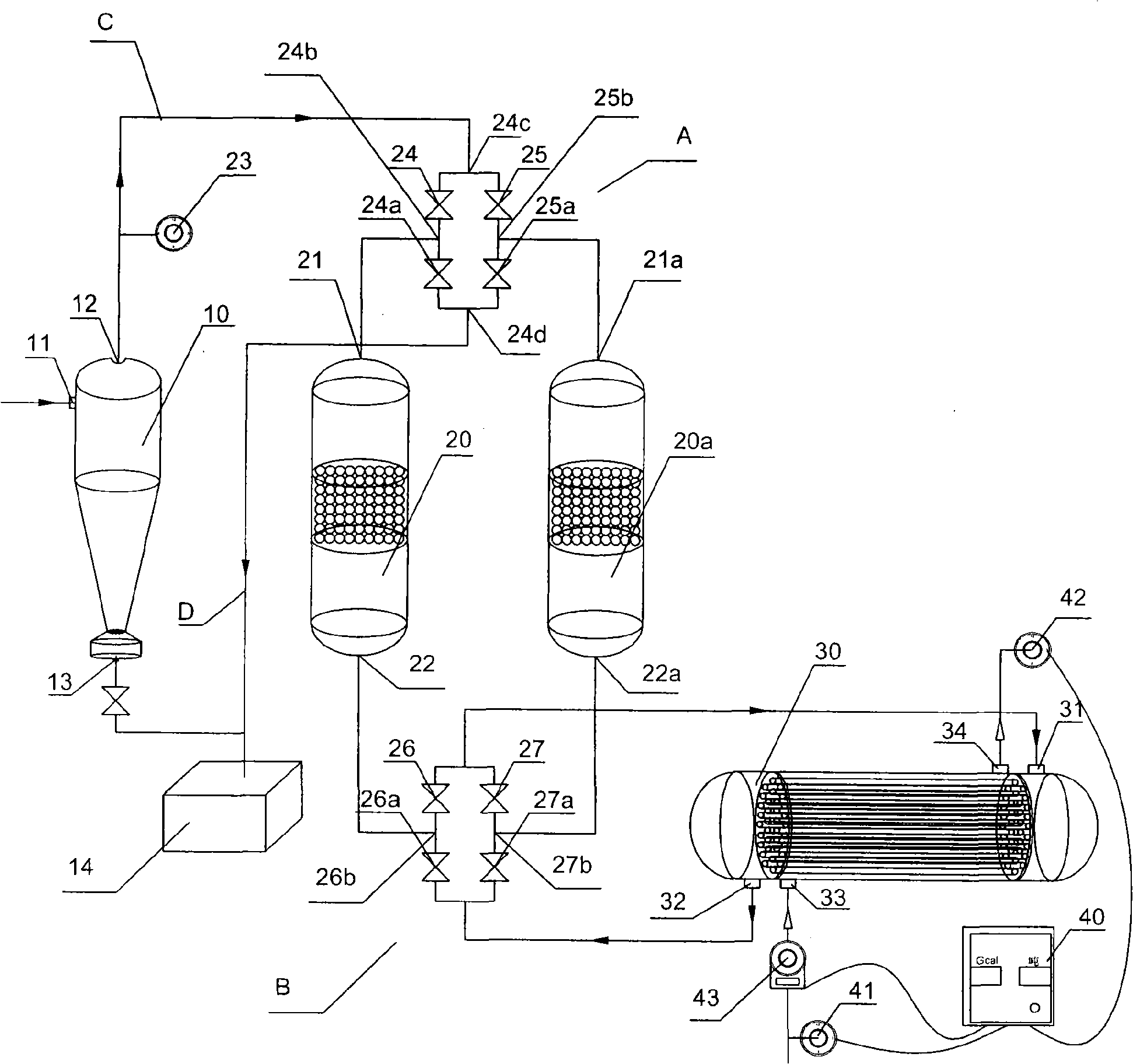
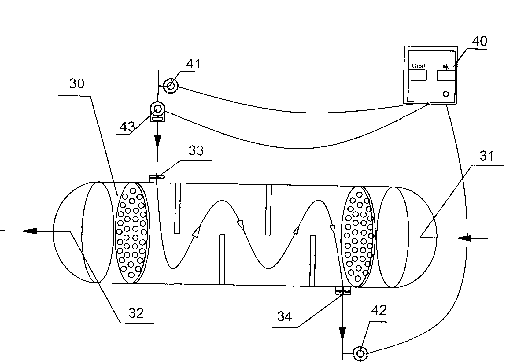
[0019] figure 1 The flow direction pointed by the middle arrow is the process flow direction of the whole equipment, the solid arrow is the flow direction of hot wastewater, and the hollow arrow is the flow direction of cold water. The medium and high-temperature wastewater discharged from the factory is firstly collected centrally, and then transported by the wastewater lift pump to the primary wastewater inlet 11 of the centrifugal filter 10. Through mechanical centrifugal force separation technology, the particulate matter in the wastewater with a specific gravity larger than water is separated from the wastewater. , the foreign matter heavier than water settles at the bottom of the centrifugal filter, and as the deposited foreign matter continues to increase, the valve of the foreign matter discharge port 13 is o...


PUM


Abstract

The invention provides a recovery system for waste hot water heat energy, belonging to the field of industrial waste water heat energy recovery. Heat energy recovery systems commonly adopted at home have the problems that heat exchange efficiency is low, a filter is not capable of automatic back flush and needs a large quantity of clear water, a heat exchanger has the problems of blockage and serious pollution and on-line display and accumulative calculation of heat energy are not feasible. The system of the invention comprises a centrifugal filtering device, a granule filtering device for automatic switch operation and back flush, a heat exchanger for heat exchange between cool water and hot water, a system for automatic switch operation and back flush of the filter, a heat energy integrating device of the whole recovery system and the like. The heat energy recovery system provided by the invention can realize automatic operation and control over back flush process of the filter, improve efficiencies in impurity filtration of the waste water and heat exchange and provide functions of accumulative calculation and on-line display of heat energy so as to realize real-time monitoring to the system performance.

Description

【Technical field】 [0001] The invention relates to a heat energy recovery system for hot waste water, which belongs to the field of heat energy recovery of industrial waste water. 【Background technique】 [0002] At present, it is common to recycle and reuse thermal energy of hot wastewater from factories at home and abroad, for example, by using heat exchange equipment including heat exchangers to reuse thermal energy. Although the heat exchangers commonly used in China for waste heat recovery can produce obvious economic and environmental benefits in theory, the actual heat exchange efficiency is low and a large amount of clean water is required. For example, some systems cannot backwash the filter, and after working for a period of time, it can only be cleaned after stopping the whole system. Someone has also adopted a heat recovery device with backwashing, but this device needs to stop the entire system to realize the backwashing function, and cannot automatically perform...

Claims


Application Information

Patent Timeline
IPC IPC(8): F28D7/10B01D36/00C02F1/00
Inventor 胡亚春甄跃进
Owner 仁新节能环保设备(上海)有限公司
Why Eureka
Try Eureka