A cold cathode focused x-ray tube

An X-ray tube and cold cathode technology, applied in the field of X-ray tubes, can solve the problems of increasing process complexity, disadvantageous X-ray imaging spatial resolution, and high working electric field, so as to reduce production costs and maintenance costs, and improve spatial resolution. , the effect of strong electron emission capability

Inactive Publication Date: 2011-12-14
SOUTHEAST UNIV
View PDF0 Cites 0 Cited by
  • Summary
  • Abstract
  • Description
  • Claims
  • Application Information

AI Technical Summary

Problems solved by technology

However, the further development of this device is limited due to its high working electric field and low working current.
The micromachining mask etching process used in it also increases the complexity of the process and increases the cost.
In addition, if the necessary focusing measures are lacking, the outgoing X-ray beam will have a large divergence angle, which is not conducive to the improvement of the spatial resolution of X-ray imaging.

Method used


Image

  • A cold cathode focused x-ray tube
  • A cold cathode focused x-ray tube
  • A cold cathode focused x-ray tube

Examples


Embodiment 1

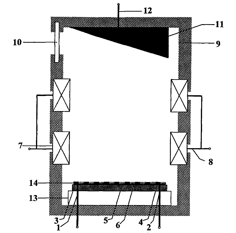
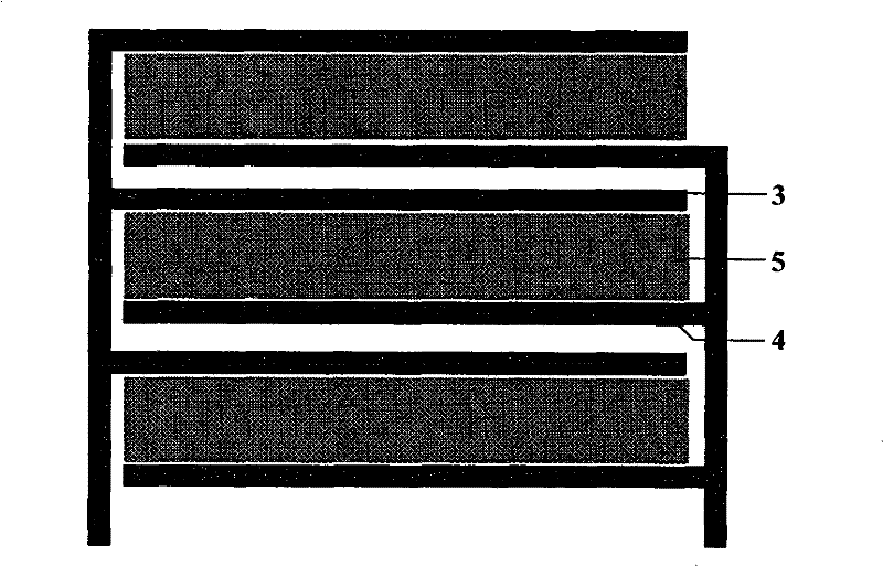
[0020] Refer to attached figure 1, the structure of the cold cathode X-ray tube in the present invention includes: a cold cathode electron source composed of a planar grid structure and a zinc oxide emitter, fixed on the bottom of the vacuum housing; an anode target made of oxygen-free copper, installed in a vacuum The top of the housing is directly above the cold cathode electron source, and the focusing electrode between the two electrodes; each electrode is connected to an external power source through a wire spot-welded on it. The lead wire of the electron source passes through the via hole reserved at the bottom of the ceramic housing to fix it. A metal electrode with a focusing structure is installed thereon, and its lower end is at a certain distance from the surface of the electron source, which is 250 microns in this embodiment. The part of the ceramic structure in contact with the metal electrode has been metallized during processing, making it easy to carry out Kov...

Embodiment 2

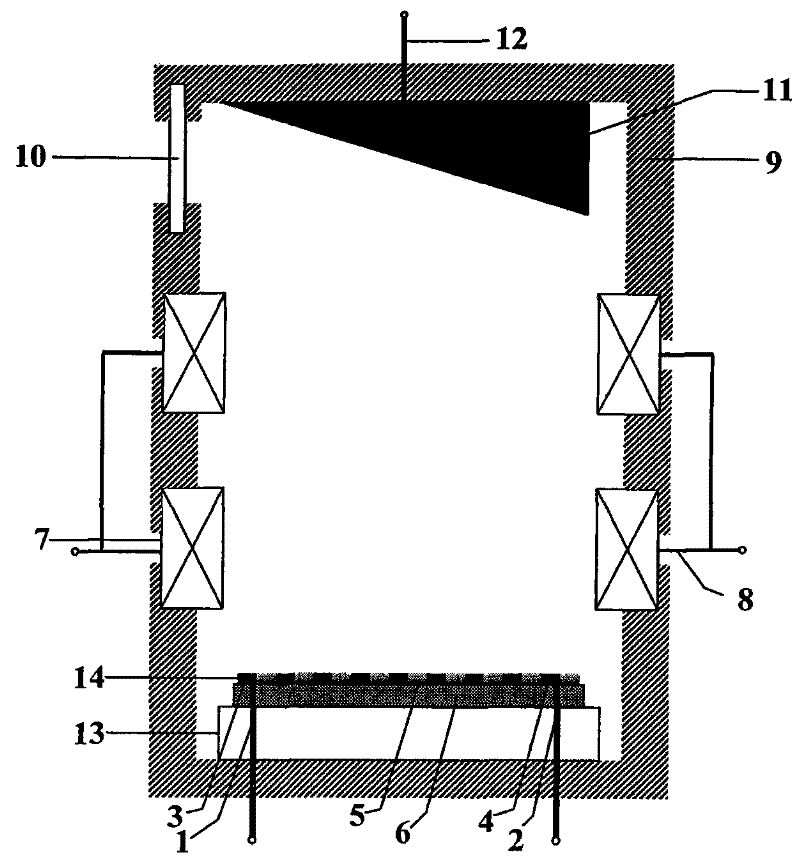
[0022] Refer to attached figure 1 , the structure of the cold cathode X-ray tube in the present invention includes: a cold cathode electron source composed of a planar grid structure and a zinc oxide emitter, which is fixed on the bottom of the vacuum housing; an anode target made of metal molybdenum is installed in the vacuum housing The top of the body is directly above the cold cathode electron source, and the focusing electrode between the two electrodes; each electrode is connected to an external power source through a wire spot-welded on it. The lead wire of the electron source passes through the via hole reserved at the bottom of the ceramic housing to fix it. A metal electrode with a focusing structure is installed thereon, and its lower end is at a certain distance from the surface of the electron source, which is 500 microns in this embodiment. The part of the ceramic structure in contact with the metal electrode has been metallized during processing, making it easy...


PUM


Abstract

The invention relates to a cold cathode focusing type X-ray tube. It includes a cold cathode electron source (14), a focusing electrode (7), a vacuum-sealed casing (9), a ray exit window (10) and a high voltage anode target (11). Zinc oxide emissive layer (5) on (14). In the present invention, the electron source is prepared on the surface of the glass substrate (6) by screen printing on the basis of a planar grid structure; the high-voltage anode target (11) is fixed directly above the electron source; the electrodes are placed in a ceramic vacuum shell Among them, it is connected to an external power supply through electrode leads. The ceramic casing is sealed in sections; a metal focusing electrode (7) is placed above the cold cathode electron source (14), and ceramics are also used for insulation and packaging between the focusing electrodes. The electron beam bombarding the surface of the anode target can be greatly compressed by the focusing electrode to realize the emission of high-resolution X-rays.

Description

technical field [0001] The invention relates to an X-ray tube, in particular to a cold cathode focusing type X-ray tube. Background technique [0002] In recent years, X-ray imaging systems have been widely used in medical fields such as diagnosis and treatment, and X-ray tubes, which are the core components of X-ray imaging systems, have also received extensive attention. Traditional X-ray tubes mostly use a filament as the electron source, that is, a hot cathode X-ray tube. By heating the filament, the internal electrons overflow to form effective electron emission. With the development of detection technology and the improvement of detection requirements, hot cathode X-ray tubes can no longer meet the high resolution and real-time requirements of modern X-ray imaging technology due to their inherent shortcomings. On the contrary, field emission cold-cathode X-ray tubes can effectively achieve real-time detection because of their characteristics such as no need for heatin...

Claims


Application Information

Patent Timeline
Patent Type & Authority Patents(China)
IPC IPC(8): H01J35/00
Inventor 迟云雁王琦龙张晓兵雷威娄朝刚
Owner SOUTHEAST UNIV
Why Eureka
Try Eureka