
Removable compressed natural gas gasification device

A technology of compressed natural gas and refueling equipment, which is applied to equipment loaded into pressure vessels, gas/liquid distribution and storage, container filling methods, etc., which can solve the problems of large investment in station construction, large land area, and difficulty in popularization, and achieve an The effect of small area, expanding applicable occasions, improving maneuverability and flexibility

Inactive Publication Date: 2009-08-05
ENRIC (LANGFANG) ENERGY EQUIP INTEGRATION CO LTD
View PDF1 Cites 6 Cited by
  • Summary
  • Abstract
  • Description
  • Claims
  • Application Information

AI Technical Summary

Problems solved by technology

This fixed refueling system needs site selection and station construction, which requires a large investment
In addition, since a separate space is required to place air compressors, control cabinets, etc., the site occupies a large area of ​​land
This makes fixed gas filling stations only suitable for places with sufficient space, and it is difficult to promote them in large cities with high demand for gas filling but limited land use area

Method used


Image

  • Removable compressed natural gas gasification device
  • Removable compressed natural gas gasification device
  • Removable compressed natural gas gasification device

Examples


Embodiment Construction

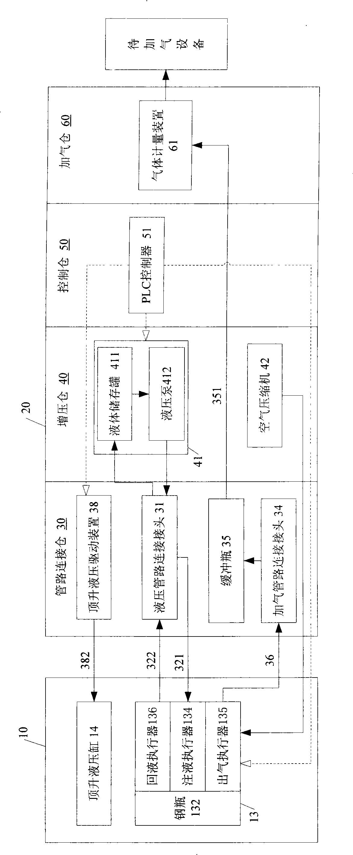
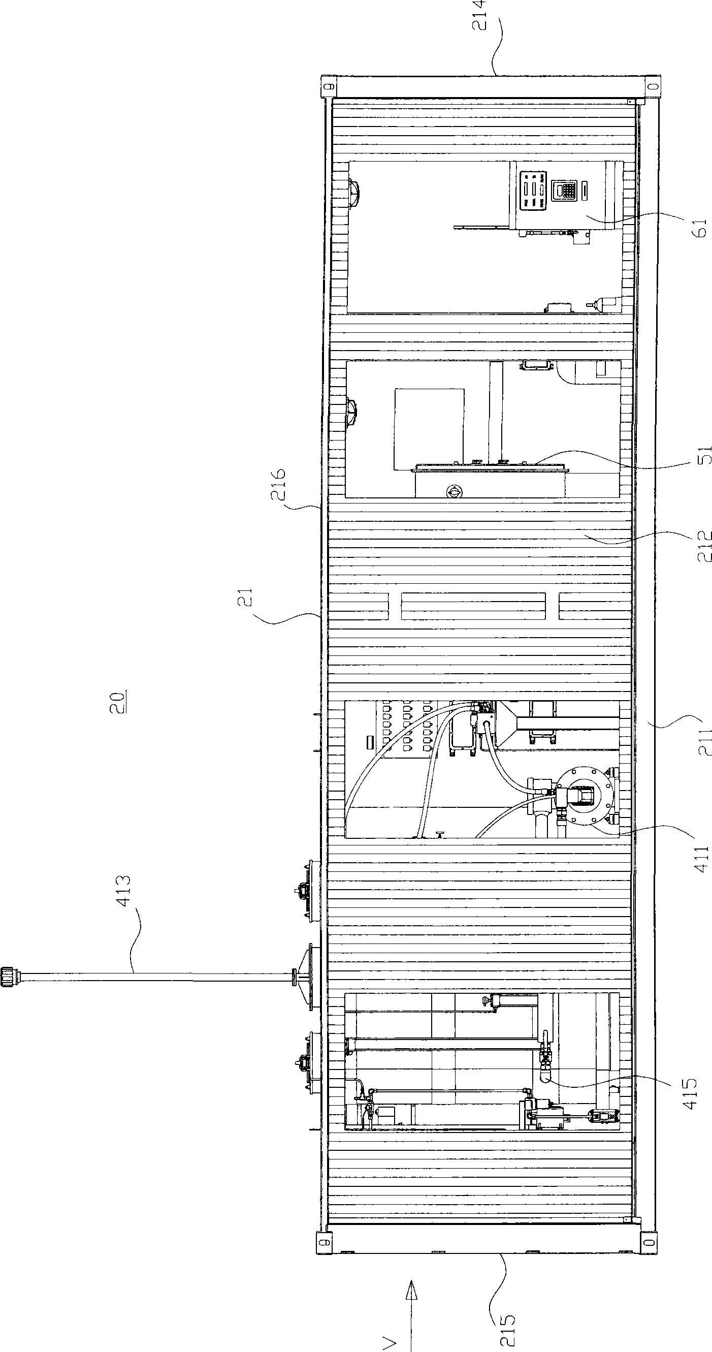
[0039] like figure 1 , 2 As shown, the mobile compressed natural gas filling device S of the present invention is mainly composed of a mobile gas source unit 10 and a mobile gas filling unit 20 .

[0040] The movable air source unit 10 includes a trailer 11 of a semi-trailer, a steel cylinder rack 12 arranged on the trailer, and one or more steel cylinder assemblies 13 fixed on the steel cylinder rack. By connecting the trailer 11 to the front of the semi-trailer, the air source unit 10 can be transported to any desired place. Each cylinder assembly 13 includes a cylinder 132 for storing compressed natural gas (CNG) and a plurality of actuators for controlling the corresponding cylinder to vent.

[0041] In one embodiment of the present invention, the actuators in each steel cylinder assembly include a liquid injection actuator 134, a gas outlet actuator 135, and a liquid return actuator 136 respectively arranged at the liquid injection port, the gas outlet port, and the liq...


PUM


Abstract

The invention discloses a movable type compressed natural gas filling device comprising a movable type gas resource unit and a movable type gas filling unit, wherein the movable type gas filling unit is provided with a box body in which a pipeline connecting chamber, a pressure boost chamber, a control chamber and a gas filling chamber are arranged; a liquid storage device is arranged in the pressure boost chamber; at least a gas metering device is arranged in the gas filling chamber; a hydraulic pipeline connector and a gas filling pipeline connector are arranged in the pipeline connecting chamber; and a controller used for controlling the gas filling process is arranged in the control chamber. The movable type compressed natural gas filling device can be freely moved to a place with power supply without the need of building a station, and is particularly suitable for bus stations, industrial enterprises and the like.

Description

technical field [0001] The invention relates to a natural gas filling device, in particular to a movable compressed natural gas filling device. Background technique [0002] As a clean energy, natural gas has been increasingly used as a fuel for motor vehicles, for example, compressed natural gas (CNG) is a common natural gas fuel. In order to refuel CNG vehicles, a dedicated fuel delivery system is required, namely a natural gas filling system. The system can be built near the natural gas pipeline network, or it can be built in a place without a pipeline network. When it is built in a place without a pipeline network, it is also called a natural gas vehicle filling station. [0003] Most of the existing refueling systems are fixed, such as the hydraulic sub-station system for natural gas vehicles disclosed in Chinese patent 200520133308.X. The refueling sub-station system includes a refueling station skid, a CNG cylinder trailer, an air compressor, a refueling machine, an...

Claims


Application Information

Patent Timeline
IPC IPC(8): F17C5/02
Inventor 李怀恩王德印顾建辉张庆志郭秀平张立改张丽敏
Owner ENRIC (LANGFANG) ENERGY EQUIP INTEGRATION CO LTD
Learn More