

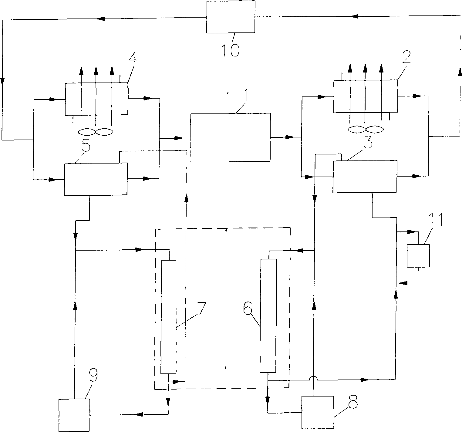
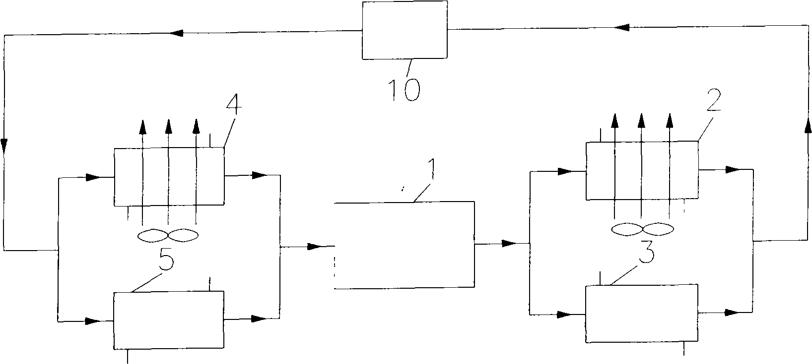
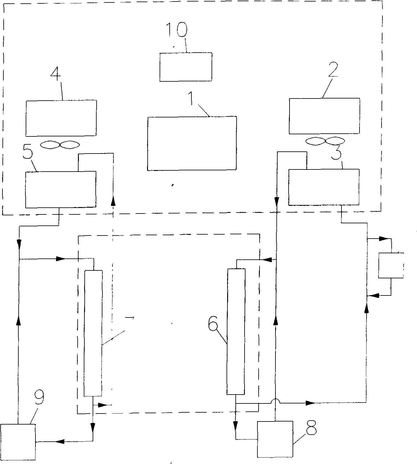
Cold/heat source integrated unit
A cold and heat source, integrated technology, applied in the direction of refrigerators, heating and cooling combinations, compressors with multiple condensers, etc., can solve the problems of low energy consumption, difficult building energy consumption, etc., to improve control quality and reduce waste heat Or waste cold discharge, improve the effect of machine dew point
- Summary
- Abstract
- Description
- Claims
- Application Information
AI Technical Summary
Problems solved by technology
Method used
Image

Examples
Embodiment 1
[0036] Example 1: The location of the cold and heat source of the hospital building and its system
[0037] The cold and heat source integrated unit of the present invention is particularly suitable for hospital buildings. Modern hospitals require the entire building to be environmentally controlled, requiring a large amount of air-conditioning chilled water and hot water. But now the amount of steam needed for sterilization is getting less and less, and the quality requirements are getting higher and higher. High-quality steam is often supplied on-site by the sterilization system, instead of relying on the steam system.
[0038] The integrated cold and heat source unit of the present invention replaces a large chiller and a boiler to become a centralized cold and heat source in a hospital, which is installed on the roof. Through the pipeline well, the hot end of the cold and heat source integrated unit is connected to the heating system, and the cold end is connected to the chill...
Embodiment 2
[0041] Example 2: The location of the hotel building's cold and heat source and its system
[0042] The integrated heat and cold source unit is also suitable for large hotel buildings. The integrated cold and heat source unit will replace the large chiller and boiler to become the centralized cold and heat source of the hotel building, which is installed on the roof. Through the pipeline well, the hot end of the cold and heat source integrated unit is connected to the heating system, and the cold end is connected to the chilled water supply system, which provides heating and cooling at the same time throughout the year, which is called a four-pipe system. The integrated cold and heat source unit supplies 7°C chilled water that can meet the needs of air conditioning throughout the year, and at the same time can provide a large amount of 55°C hot water for bathing. In addition to requiring a lot of hot water for bathing, hotel buildings are also becoming larger and larger like moder...
PUM
 Abstract
Description
Claims
Application Information