Heat pipe performance detection apparatus

A detection device and heat pipe technology, which can be used in measurement devices, calorimeters, and heat measurement, etc., can solve the problems of increasing mass production of detection devices and labor costs, frequent reuse, and heat pipe performance variation.

Inactive Publication Date: 2009-08-05
FU ZHUN PRECISION IND SHENZHEN +1
View PDF0 Cites 11 Cited by
  • Summary
  • Abstract
  • Description
  • Claims
  • Application Information

AI Technical Summary

Problems solved by technology

[0007] However, the above figure 1 and other existing heat pipe performance detection devices generally have the following shortcomings, which are not conducive to accurately evaluating the performance of heat pipes; including:
[0008](1) In order to achieve the close thermal contact between the heat pipe, the heat source and the heat sink, and to accurately measure the wall temperature of the evaporation section and the condensation section of the heat pipe at the same time, the current detection The device is difficult to balance;
[0009](2) The above requirements are more difficult to effectively control when multiple detection devices are used in mass production;
[0010](3) It is difficult to accurately control the effective length of the evaporating section and the condensing section during the rapid full inspection, which is another important factor causing the variation of the performance of the heat pipe;
[0011](4) Heat loss and temperature measurement are susceptible to variation due to the influence of the external environment;
[0012] (5) Installation and disassembly are very cumbersome and labor-intensive, so that the heat pipe performance testing device in the prior art is only suitable for small-scale heat pipe testing on a laboratory scale, and cannot meet the testing requirements required by the mass pr

Method used


Image

  • Heat pipe performance detection apparatus
  • Heat pipe performance detection apparatus
  • Heat pipe performance detection apparatus

Examples


Embodiment Construction

[0030] The following reference Figure 2 to Figure 11 , The heat pipe performance detection device of the present invention will be further explained.

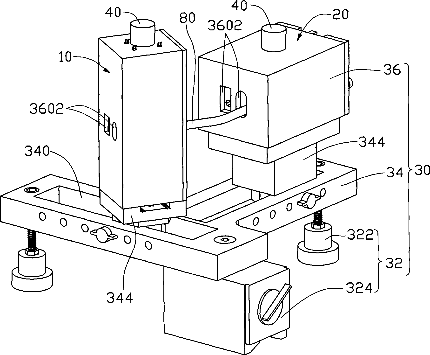
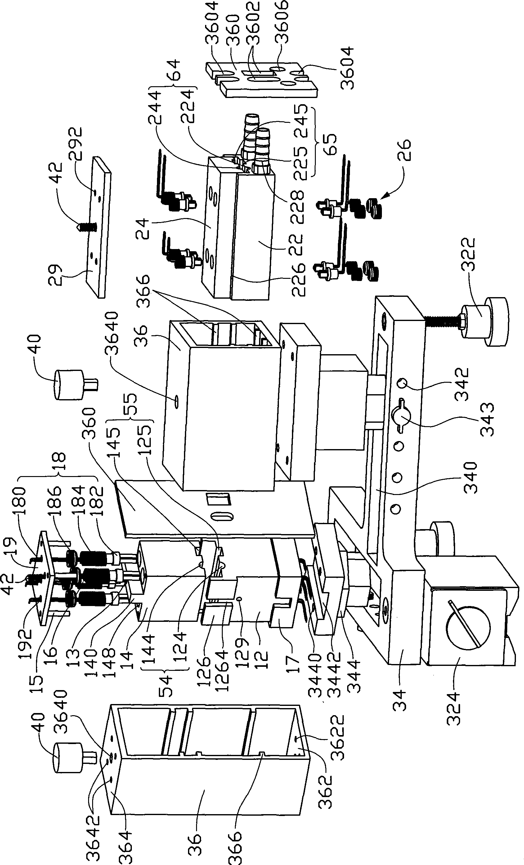
[0031] figure 2 Is a three-dimensional schematic diagram of the appearance of the first embodiment of the heat pipe performance detection device of the present invention, image 3 for figure 2 A three-dimensional exploded schematic diagram of Figure 4 for figure 2 A three-dimensional schematic diagram of the appearance of the fixed part of the heating assembly, Figure 5 for Figure 4 A three-dimensional exploded schematic diagram of. The detection device mainly includes a heating component 10, a heat dissipation component 20 and a supporting base 30. among them:

[0032] The heating assembly 10 includes a fixed part 12 and a movable part 14. The fixed part 12 is a fixed part that is locked to a stable platform such as a test table or other supporting mechanism. At least one of the fixed portion 12 and the movable portion 14 is...


PUM


Abstract

The invention discloses a thermotube performance detecting device comprising a heating component, a radiating component and a bearing part. The heating component and the radiating component respectively comprise a fixed part and a movable part which can be separable and inseparable from each other; at least one measuring and accommodating part capable of accommodating a thermotube to be measured is arranged between the opposite surfaces of the heating component and the radiating component; the measuring and accommodating part is internally provided with at least one temperature sensor; the heating component is provided with at least one heating element for heating the evaporating section of the thermotube to be measured; the radiating component is provided with at least one cooling structure; the bearing part comprises one positioning seat and two clamping seats which are arranged on the positioning seat and bear the heating component and the radiating component respectively, wherein at least one clamping seat adjusts the relative angel of the measuring and accommodating part arranged between the heating component and the radiating component with respect to the preset rotation angle of the positioning seat so as to bend thermotubes to be measured differently.

Description

Technical field [0001] The invention relates to a detection device, in particular to a heat pipe performance detection device. Background technique [0002] The basic structure of the heat pipe is to line the inner wall of the closed pipe with a porous capillary structure layer that easily absorbs the actuating fluid, and the central space is hollow, and the evacuated closed pipe is filled with a total of pores equivalent to the capillary structure layer. The volume of the actuating fluid can be divided into the evaporation section, the condensation section and the adiabatic section in between according to the relative position of the absorption and dissipation of heat. [0003] The working principle of the heat pipe is that when the evaporation section absorbs heat to evaporate the liquid-phase actuating fluid contained in the capillary structure layer and increase the vapor pressure, the high-enthalpy vapor flow generated is quickly moved along the central channel to the lower ...

Claims


Application Information

Patent Timeline
IPC IPC(8): G01N25/20G01N25/18G01M19/00G01M99/00
CPCG01K17/00F28F2200/005
Inventor 刘泰健
Owner FU ZHUN PRECISION IND SHENZHEN
Why Eureka
Try Eureka