Method and apparatus for forming amorphous coating film

An amorphous and coating technology, applied in the direction of spraying devices, liquid spraying devices, metal material coating technology, etc., can solve the problem of lowering the minimum reaching temperature, it is difficult to achieve cooling speed, and the industrial scale mass production of amorphous metal thermal spraying has not been established Methods and other issues

An amorphous and coating technology, applied in the direction of spraying devices, liquid spraying devices, metal material coating technology, etc., can solve the problem of lowering the minimum reaching temperature, it is difficult to achieve cooling speed, and the industrial scale mass production of amorphous metal thermal spraying has not been established Methods and other issues

CN101501236AActive Publication Date: 2009-08-05臼井株式会社 +1

Image

  • Method and apparatus for forming amorphous coating film
  • Method and apparatus for forming amorphous coating film
  • Method and apparatus for forming amorphous coating film

Examples


Embodiment Construction

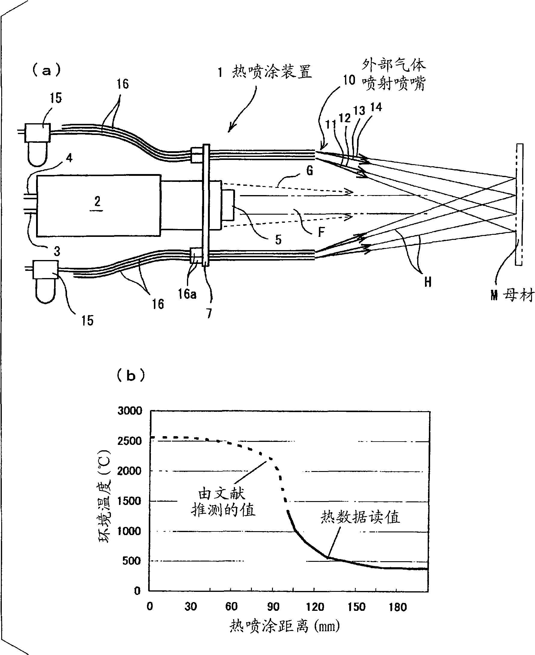
[0106] refer to Figure 1 to Figure 14 One embodiment of the present invention will be described.

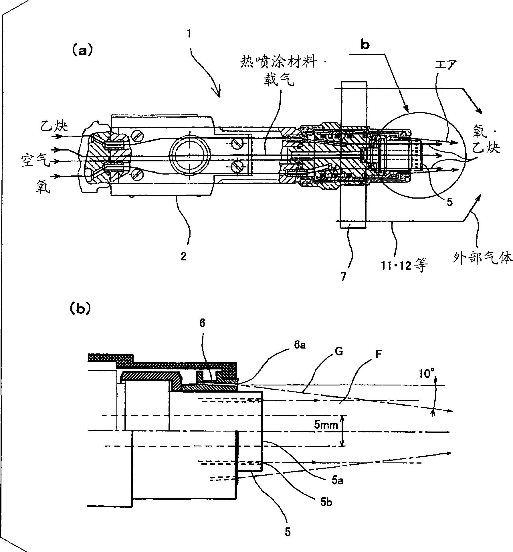
[0107] First, based on figure 1 · figure 2 The configuration of the thermal spraying apparatus 1 will be described. Thermal spraying device 1 is based on commercially available thermal spraying gun 2, supplies fuel (acetylene and oxygen) by gas supply pipe 3 etc., supplies metal powder and carrier gas by powder supply pipe 4 simultaneously, can contain thermal spraying material (by The flame F of the material formed by melting the supplied metal powder) is injected from the main nozzle (burner port) 5 of the thermal spray gun 2 to the right in the figure. main nozzle 5, by figure 2 (b) The ejection port 5a in the central part ejects the thermal spraying material, and the flame F formed by the combustion of a mixed gas containing acetylene and oxygen (or air) is ejected from a plurality of ejection ports 5b around it.


PUM

PropertyMeasurementUnit
particle diameteraaaaaaaaaa
thicknessaaaaaaaaaa

Abstract

A method and apparatus for forming an ordinary amorphous coating film not limited to metallic glasses, etc. by thermal spraying.A flame (F) containing material particles is ejected from a nozzle (5) toward a base material (M). The material particles are melted by the flame (F), and these material particles and the flame (F) begin to be cooled before they reach the base material (M).For the cooling, a gas (H) is blown from outer peripheral areas apart from the flame (F) so that the gas (H) approaches the center line for the flame (F). It is preferable that the material particles in the flame (F) have a particle diameter of 10-100 [mu]m.

Description

[0001] Cross-reference of related applications [0002] This application claims the priority of Japanese Patent Application No. 2006-221112 and Japanese Patent Application No. 2007-8477, and the entire contents of the aforementioned Japanese Patent Applications are incorporated herein by reference. technical field [0003] The present invention relates to forming an amorphous (amorphous material) film on the surface of a base material such as a metal by thermal spraying, and to a method and an apparatus for forming an amorphous film by thermal spraying. Background technique [0004] Amorphous (non-crystalline) metals are metals that have an irregular atomic arrangement different from the crystalline state. Since they have high mechanical strength, corrosion resistance, and excellent magnetic properties, various researches and developments are being conducted on their production methods and applications. Various techniques for forming an amorphous coating on the surface of an...

Claims


Application Information

Patent Timeline
05 Aug 2009
Publication
CN101501236A
IPC
C23C4/12; B05B7/20
Inventors
仓桥隆郎; 小牧正博