Superhard material cutting tool and preparation method thereof

A cutting tool and superhard material technology, applied in the field of superhard material cutting tools, can solve the problem of difficult removal of floor coatings, and achieve the effect of ensuring smoothness, small friction coefficient and high wear resistance

Active Publication Date: 2009-08-12
ADVANCED TECHNOLOGY & MATERIALS CO LTD +1
View PDF1 Cites 7 Cited by
  • Summary
  • Abstract
  • Description
  • Claims
  • Application Information

AI Technical Summary

Problems solved by technology

[0006] The purpose of the present invention is to provide a cutting tool for superhard materials, which solves the problem that the floor paint is difficult to remove, has high hardness, good thermal stability, chemical inertia and appropriate toughness, does not produce tumor accumulation during cutting, and has no No burrs, no scratches, no haze and chatter marks, which can meet the needs of modern superhard material processing

Method used


Image

  • Superhard material cutting tool and preparation method thereof
  • Superhard material cutting tool and preparation method thereof
  • Superhard material cutting tool and preparation method thereof

Examples


Embodiment 1

[0023] Figure 1 ~ Figure 3 It is a specific embodiment in the present invention.

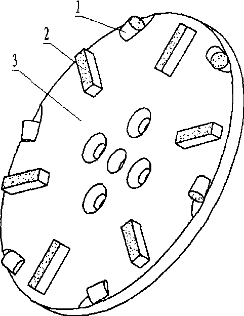
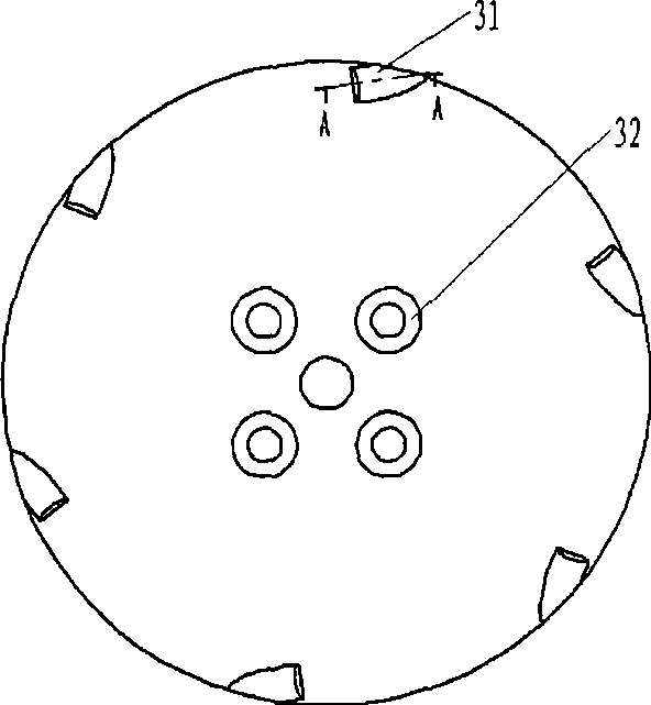
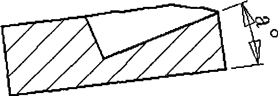
[0024] figure 1 It is a schematic diagram of the structure of the tool. The tool head is composed of two parts, polycrystalline diamond composite sheet 1, diamond pre-alloyed powder head 2, and steel matrix 3. The steel matrix is ​​disc-shaped see figure 2 , equipment mounting holes 32 are distributed in the middle of the disk-shaped substrate, and oblique cylindrical grooves are punched on the periphery of the disk for welding polycrystalline diamond composite sheets. The A-A sectional view of the cylindrical groove is shown in image 3 As shown, the angle between the centerline of the cylindrical groove and the surface of the substrate (that is, the cutting surface) is a, and the value of a is (0-30)°.

[0025] In the design of the welded joint structure, the polycrystalline diamond composite sheet 1 is a cylinder, and the edge area of ​​the composite sheet provides a cutting edge for the...

Embodiment 2

[0028] Figure 4 It is another superhard material cutting tool of the present invention. The steel matrix 3 of this cutting tool is disc-shaped, and an oblique cylindrical groove is cut on the outer edge of the disc matrix for welding polycrystalline diamond composite sheet 1. The cylindrical groove structure Same as Example 1; the diamond tip 2 used for grinding in this cutting tool is trapezoidal, and the production process of the cutting tool is as described in Example 1.

Embodiment 3

[0030] Figure 5 It is another superhard material cutting tool of the present invention. The steel matrix 3 of this cutting tool is disc-shaped, and an oblique cylindrical groove is cut on the outer edge of the disc matrix for welding polycrystalline diamond composite sheet 1. The structure of the cylindrical groove is the same as Example 1 is the same; the diamond bit 2 used for grinding in this cutting tool is in the form of a cylinder, and the production process of the tool is as described in Example 1.


PUM


Abstract

The invention relates to a superhard material cutting tool and a preparation method thereof, which belongs to the technical field of superhard material. The superhard material cutting tool comprises a steel matrix and a cutting tool bit. The cutting tool bit consists of a polycrystalline diamond compact (1) and a diamond tool bit (2); 1 to 12 inclined cylindrical tanks used for welding the diamond compact are distributed on the outer circle surface of the steel matrix, and the center line of the inclined cylindrical tank forms a cutting angle with the cutting face; the diamond tool bit is welded on the surface of the steel matrix. The polycrystalline diamond compact is combined by PCD and cemented carbide matrix and is sintered from the mixture of diamond and the metal powder after being compacted; the structure thereof is in the shape of cylinder, ladder or squareness; the fringe area of the clad compact is the cutting blade. The superhard material cutting tool solves the materials hard to be processed in the cutting field, and ensures the surface of the machined part free of burr, nick, spray and chatter mark; the cutting and grinding combination not only improves the cutting speed, but also ensures the cutting quality.

Description

technical field [0001] The invention belongs to the technical field of superhard materials, and in particular relates to a cutting tool for superhard materials and a method for removing floor paint by using the tool. Background technique [0002] With the development of material technology and manufacturing technology, various high-performance new materials are constantly emerging, which requires cutting tools to have high hardness, thermal stability, chemical inertness and appropriate toughness, thus bringing great challenges to traditional diamond tools . [0003] 200820123065.5 discloses a clamping diamond grinding disc. The grinding disc is inlaid on the base of the grinding disc through the dovetail wedge of the grinding head. The grinding head and the base of the grinding disc will be automatically locked with the grinding rotation of the grinding disc. There are deep trapezoidal grooves for easy chip removal and cooling. The grinding disc cutter head adopts powder m...

Claims


Application Information

Patent Timeline
Patent Type & Authority Applications(China)
IPC IPC(8): B23P15/28B23K1/002B23K101/20
Inventor 罗晓丽黄盛林赵刚刘一波杨合丹姚炯彬杨志威
Owner ADVANCED TECHNOLOGY & MATERIALS CO LTD
Why Eureka
Try Eureka