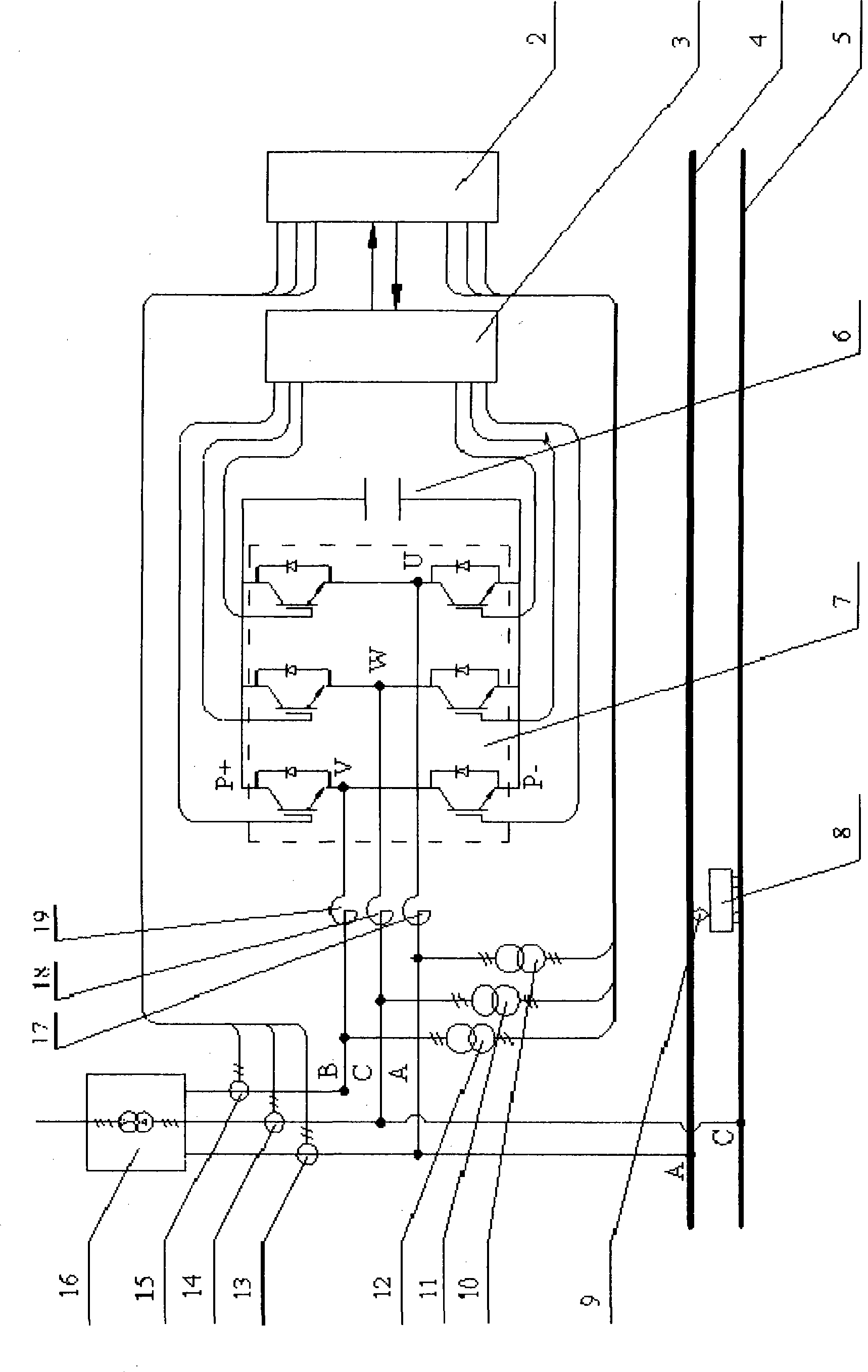
Non phase separation type traction power supply equipment for railway locomotive

A technology for traction power supply and railway locomotives, applied in power lines, vehicle components, transportation and packaging, etc., can solve the problem of large negative sequence current value and grid harmonic content, small distance between traction substations, and impossible three-phase balance Power supply and other issues, to achieve the effect of less harmonic content, improve utilization efficiency, and improve power supply quality

CN101503065AInactive Publication Date: 2009-08-12四川省佳灵电气有限公司
0 Cites 7 Cited by

Patent Information

Authority / Receiving Office
CN · China
Current Assignee / Owner
Publication Date
2009-08-12
Estimated Expiration
Not applicable · inactive patent

Smart Images

  • Figure 1
    Figure 1
Patent Text Reader

Abstract

A non-split-phase type traction power supply device used for rail vehicles belongs to technical field of railway electric traction power supply. The device comprises a traction transformator and an energy distribution regulating machine which mainly consists of a main controller, a driver, an electronic power switch bridgearm, a support capacitance arm, three electric current sensors, three voltage transducers and three reactors, wherein, the driver is connected between a control terminal of the electronic power switch bridgearm and the main controller, the electric current sensors and the voltage transducers are respectively connected between the main controller and A phase, B phase and C phase of an output end of the traction transformator, and the reactors are connected between the center of the bridgearm and the A phase, the B phase and the C phase of an output end of the traction transformator. The invention has the advantages that split-phase power supply is changed into non-split-phase power supply, great run-through of the traction contact network can be realized, and power phase position exchange for power supply again caused by frequent power failure can be avoided, so that safe, high speed and high-efficiency running of train can be guaranteed.
Need to check novelty before this filing date? Find Prior Art

Description

technical field

[0001] The invention relates to a railway locomotive traction power supply device. It belongs to the technical field of railway electric traction power supply. Background technique

[0002] As we all know, power plants provide three-phase AC power, while electrified railway traction power supply systems use two-phase power supply to reduce costs, and use segmented and different-phase power supply methods, that is, phase-separated power supply, to balance the three-phase. Most of the power supply methods of railway traction systems at home and abroad adopt the YNd11 power supply method and the improved method (Scott) based on it, and they all belong to the out-of-phase power supply (separate phase power supply) method as a whole. (See p.126-131 in the book "High-Speed ​​Railway Electrification Engineering" published by Southwest Jiaotong University Press and p.10-15 in the book "Analysis of Traction Power Supply System"). In this split-phase power supply mod...

Examples

Embodiment Construction

[0008] Attached below figure 1 The present invention is described in detail.

[0009] see figure 1 , the non-phase-splitting traction power supply device for the railway locomotive is composed of a traction transformer and an energy distribution regulator, the A phase of the output end of the traction transformer 16 is connected to the traction catenary 4, the C phase is connected to the rail 5, and the B phase is connected to the energy distribution Regulator, the energy distribution regulator consists of a main controller 2, a driver 3, three current sensors 13, 14, 15, three voltage sensors 10, 11, 12, three reactors 17, 18, 19, power The electronic switch bridge arm 7 and the supporting capacitor arm 6 are composed, wherein the power electronic switch bridge arm 7 is connected in parallel with the supporting capacitor arm 6, and the driver 3 is connected between the control terminal of the power electronic switch bridge arm 7 and the main Between the controllers 2, the s...