Pulse width frequency modulation mode DC/DC boosting circuit

A pulse width and frequency adjustment technology, which is applied in the direction of adjusting electrical variables, control/regulation systems, electrical components, etc., can solve problems such as excessive output voltage or current

Inactive Publication Date: 2009-08-12
天津英诺华微电子技术有限公司
View PDF0 Cites 9 Cited by
  • Summary
  • Abstract
  • Description
  • Claims
  • Application Information

AI Technical Summary

Problems solved by technology

[0005] In view of the above-mentioned problems in the prior art, the present invention proposes a pulse width frequency regulation mode DC / DC boost circuit, which corresponds to different operating frequency PWM modes according to different situations of light or heavy loads, and in this The error voltage feedback loop is added to the boost circuit, which not only combines the advantages of PFM and PWM, but also solves the problem of output voltage or current caused by the PFM boost circuit being unable to turn off the PMOS when the input is higher than the output. too high problem

Method used


Image

  • Pulse width frequency modulation mode DC/DC boosting circuit
  • Pulse width frequency modulation mode DC/DC boosting circuit
  • Pulse width frequency modulation mode DC/DC boosting circuit

Examples


Embodiment Construction

[0023] Below in conjunction with accompanying drawing, technical scheme of the present invention is described in further detail:

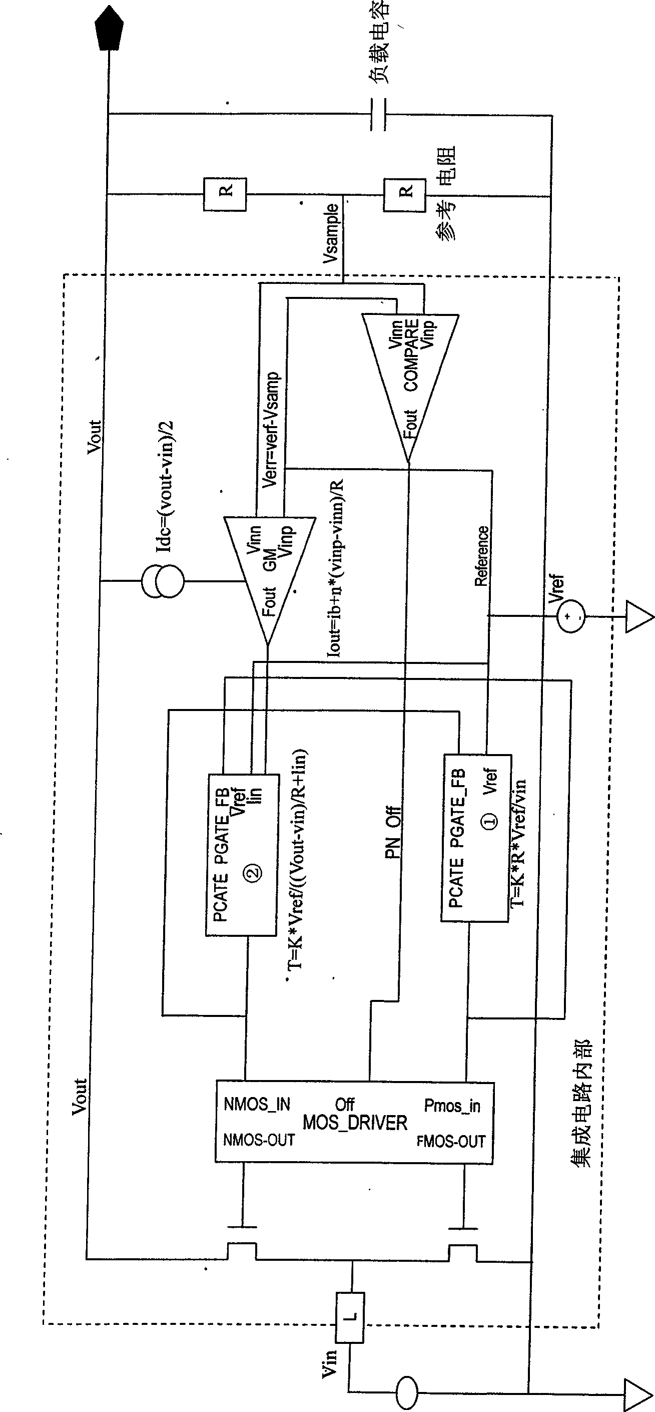
[0024] In the DC / DC boost circuit of the pulse width frequency regulation mode of the present invention, a power switch tube (PMOS_pulse_generator, NMOS_pulse_generator) module is used to generate a control signal, and the control signal is then passed through a power switch transistor driver (MOS_Diver) to control the MOS tube to turn on And shut down, so as to realize the DC / DC conversion from input to output.

[0025] like figure 1 Shown, is the circuit diagram of the DC / DC step-up circuit of the pulse width frequency regulation mode of the present invention, and its working principle is: DC input voltage V in A coil is coupled with the power switching tubes NMOS and PMOS, the other end of the NMOS tube is grounded, the other end of the PMOS tube is coupled with the load, and the other end of the load is grounded. The output voltage gets the s...


PUM


Abstract

The invention discloses a pulse width frequency regulation mode DC/DC booster circuit, which has the combined advantages of PFM and PWM and is provided with an error voltage feedback circuit. When the load is lighter, the system operates in a split state represented by the PFM mode with high efficiency. When the load is heavy, the system operates in a continuous state represented by the PWM mode, and as the error voltage feedback circuit is added, the load carrying capacity of the system is improved obviously. Meanwhile, compared with a PFM/PWM control mode (the starting duration of NMOS is determined only an input voltage, while the starting duration of the PMOS is determined only by the different of an output voltage and the input voltage), the design avoids the problem that when the input is higher than the output, the PFM/PWM mode fails to turn off the PMOS.

Description

technical field [0001] The present invention relates to a DC / DC converter, in particular to a DC / DC step-up circuit combining pulse frequency modulation (PFM) and pulse width modulation (PWM) working modes according to load conditions. Background technique [0002] Due to its outstanding features such as small size, low price, and high energy conversion efficiency, DC / DC converters have always been at the core of the design of high-efficiency and energy-saving switching power supplies, and are widely used in various power management systems. With the continuous development of the industry, DC / DC conversion technology and corresponding chip design methods are also constantly updated, and various ingenious control strategies emerge in endlessly. [0003] In the prior art, a pulse generating circuit is a key component of a DC / DC boost circuit, and its working principle mainly includes PWM (pulse width modulation) and PFM (pulse frequency modulation). These two different pulse ...

Claims


Application Information

Patent Timeline
Patent Type & Authority Applications(China)
IPC IPC(8): H02M3/155
Inventor 褚以人
Owner 天津英诺华微电子技术有限公司
Why Eureka
Try Eureka