Gasifying device for liquid fuel or solid fuel aqueous slurry

A technology of solid fuel and gasification device, which is applied in the direction of granular/powder fuel gasification, joint combustion mitigation, and production of combustible gas, etc. It is difficult to increase the pressure and other problems, so as to achieve uniform gas residence time, improve sensible heat utilization efficiency, and improve coal gasification efficiency.

Active Publication Date: 2009-08-19
WISON ENG +1
View PDF4 Cites 26 Cited by
  • Summary
  • Abstract
  • Description
  • Claims
  • Application Information

AI Technical Summary

Problems solved by technology

Disadvantages of the Shell process include: using dry pulverized coal as feed material, it is difficult to transport the pulverized coal, it is difficult to accurately measure the amount of pulverized coal entering the gasifier, and it is difficult to increase the pressure of the gasification reaction. Reduce the cycle gas compression work consumption and reduce the overall dust removal efficiency
The two-stage gasifier of Northwest Institute of Thermal Engineering has improved the high-temperature crude gas quenching method of Shell, and added two nozzles at the exit of the high-temperature zone, injecting pulverized coal and steam, and using high-temperature sensible heat for coal pyrolysis React with gasification, and use steam and pulverized coal to quench the high-temperature crude gas to 900°C. The disadvantage is that because the temperature of the second stage reaction is between 900-1000°C, the gasification temperature is low, and the methane in the crude gas The content is too high, pulverized coal can not fully react, the gas dust content is high, etc.

Method used


Image

  • Gasifying device for liquid fuel or solid fuel aqueous slurry
  • Gasifying device for liquid fuel or solid fuel aqueous slurry
  • Gasifying device for liquid fuel or solid fuel aqueous slurry

Examples


Embodiment 1

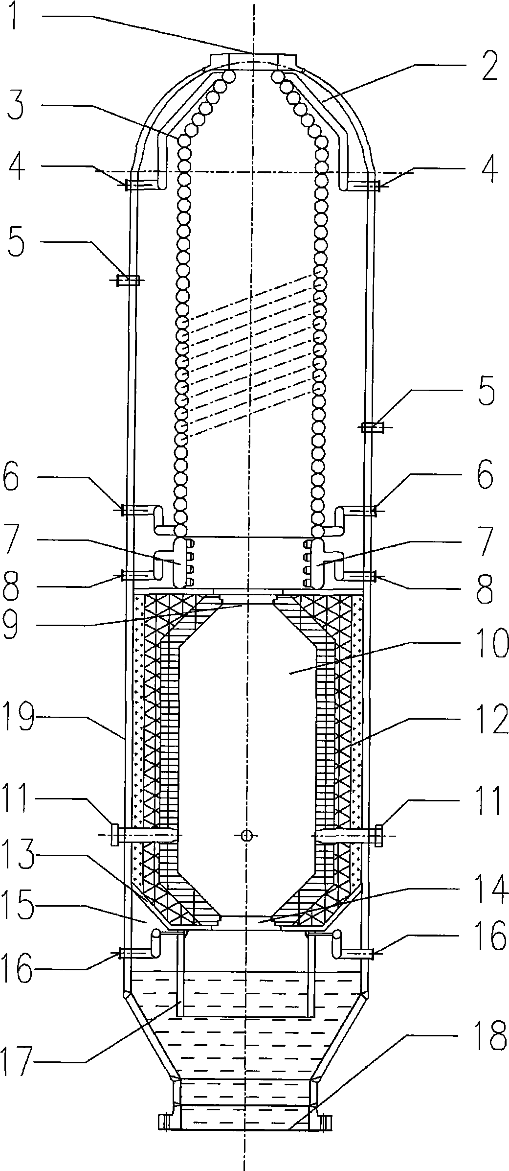
[0027] Such as figure 1 As shown, a gasification device for liquid fuel or solid fuel water slurry, the gasification furnace shell 19 of the gasification device is an upright cylinder, and the internal structure of the gasification furnace shell 19 is divided into three sections, from top to bottom The gas cooling chamber 2 , the gasification chamber 10 and the slag collection chamber 15 are respectively connected in the lower gasification furnace shell 19 coaxially.

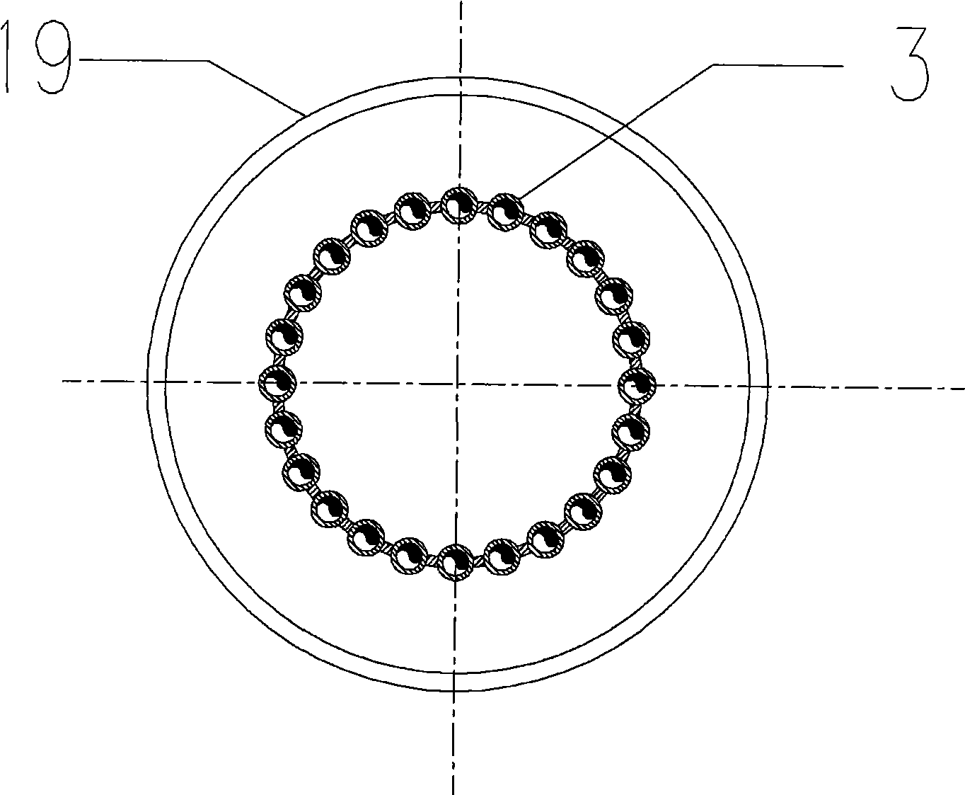
[0028] A water-cooled wall boiler 3 is installed in the gas cooling chamber 2, and the water-cooled wall boiler 3 can adopt coiled tubes or vertical bundled tubes or water jackets.figure 1 It is the case that the water-cooled boiler 3 adopts a coil, image 3 This is the case where the water-cooled boiler 3 adopts vertical bundled tubes, and the tubes are connected by welding, such as Figure 4~5 as shown, Figure 6 This is the case where the water-cooled wall boiler 3 adopts a water jacket. The upper end of th...


PUM


Abstract

The invention relates to a gasifying device of liquid fuel or solid fuel water slurry. The gasifying device comprises a gasification furnace housing (19) that is a right cylinder, and the internal structure is divided into three segments that are respectively a gas cooling chamber (2), a vaporizing chamber (10) and a cinder collection chamber (15) from top to bottom; the three chambers are vertically and axially connected in the gasification furnace housing (19); the top of the gasification furnace housing (19) is provided with a gas outlet (1), and the bottom is provided with a cinder equipment interface (18). Compared with the prior art, the gasifying device has the advantages of simple structure, easy manufacture, low investment cost, etc.

Description

technical field [0001] The invention relates to a gasification device for liquid fuel or solid fuel water slurry, in particular to a gasification device for producing crude gas with liquid hydrocarbon or coal water slurry. Background technique [0002] The clean and efficient utilization of coal is a major technical issue in the field of energy and environmental protection today, and it is also one of the key technologies for the sustainable development of my country's national economy. [0003] Coal gasification technology is divided into two types according to the feeding method, one is the dry coal powder gasification process (ZL02829258.8) represented by the Dutch Shell (Shell) company, and the other is the US GE (formerly Texaco (Texaco) )) The coal water slurry coal gasification process represented by the company (ZL94117093.4). [0004] In recent years, the domestic coal chemical industry has made great progress, and a number of coal gasification processes with indep...

Claims


Application Information

Patent Timeline
Patent Type & Authority Applications(China)
IPC IPC(8): C10J3/48
CPCY02E20/18C10J3/845C10J3/526C10J3/76
Inventor 赵柄国邹永胜方邦吾李保有唐卫兵席文洪刘洪钧朱长城
Owner WISON ENG
Why Eureka
Try Eureka