Ripple glaze arch bar, steel bar longeron and concrete combined arch shell structure

A reinforced truss and concrete technology, which is applied to arch structures, dome roof structures, building components, etc., can solve the problems of poor local impact resistance, labor and time-consuming, and elimination, and achieve high local impact resistance. The effect of good overall performance and high overall resistance

Inactive Publication Date: 2009-08-19
TSINGHUA UNIV
View PDF0 Cites 6 Cited by
  • Summary
  • Abstract
  • Description
  • Claims
  • Application Information

AI Technical Summary

Problems solved by technology

[0002] Reinforced concrete arch shells and steel structure arches have been very common in civil engineering applications, but they have the following disadvantages: (1) Reinforced concrete arch shells must use a support formwork system during the construction process, which consumes a large amount of formwork materials and formwork works. It is extremely large, labor-intensive and time-consuming, which increases the cost of the structure construction process and is gradually eliminated in civil engineering; (2) when the solid-web cross-section steel arch is formed, it can only be formed due to the large plastic deformation of the component web. Arc shape, no matter cold working or hot working, its forming process is extremely difficult; (3) If you want to build a protective project with strong impact load capacity, reinforced pure concrete arch shell or pure steel structure arch will not be able to complete this mission
Although the latter has good ductility, other structural materials still need to be filled between the steel arches, so the bearing capacity is low and cannot withstand large impact loads, and the local impact resistance is poor, which cannot meet the functional requirements

Method used


Image

  • Ripple glaze arch bar, steel bar longeron and concrete combined arch shell structure
  • Ripple glaze arch bar, steel bar longeron and concrete combined arch shell structure

Examples


Embodiment Construction

[0012] The present invention will be described in detail below in conjunction with the accompanying drawings.

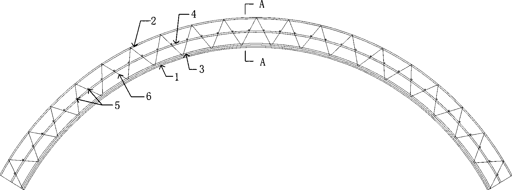
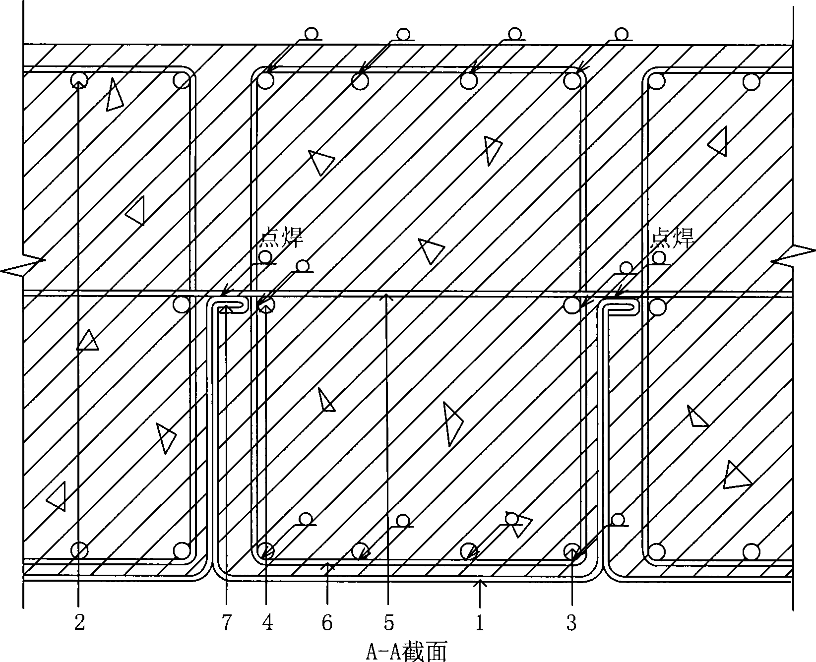
[0013] Such as Figure 1~2 As shown, 1- corrugated arch plate 2- upper chord longitudinal reinforcement 3- lower chord longitudinal reinforcement 4- web reinforcement 5- transverse reinforcement 6- web bar 7- corrugated arch slab undercut.

[0014] The corrugated arch plate, steel bar truss arch and concrete composite arch shell structure of the present invention is composed of corrugated arch plate 1, steel bar truss and concrete. The corrugated arch plate can be combined into an arch shell of any length through the undercut 7, and the upper chord longitudinal rib 2, the lower chord longitudinal rib 3, and the web tendons can form a reinforced truss arch by welding with obliquely placed web bars. The transverse steel bar is welded (or bound) to the steel bar truss arch, and connected by spot welding at the joint 7 of the corrugated arch plate. Therefore, the corru...


PUM

PropertyMeasurementUnit
diameteraaaaaaaaaa

Abstract

The invention relates to a novel combination arc shell structure consisting of a ripple arc plate, a steel bar truss and concrete, belonging to the technical field of constructional engineering. The arc shell structure comprises the ripple arc plate, the steel bar truss and the concrete. The steel bar truss is composed of upper chord longitudinal bars, lower chord longitudinal bars, web bars, web members and transverse steel bars; the ripple arc plates are assembled into arc shells of any length by ripple arc plate undercut; welding or colligation can be carried out on the transverse steel bars and a steel bar truss arch; and the transverse steel bars and the steel bar truss arch can be connected at the occlusion part of the ripple arc plate by spot welding; the ripple arc plate and the steel bar truss arch form an arc die plate system, and then concrete is poured; after the concrete is solidified, the combination arc shell structure consisting of the ripple arc plate, the steel bar truss and the concrete is obtained. The combination arc shell structure of the invention has good overall performance and high carrying capacity, facilitates outdoor construction and saves cost; in addition, the structure has very good overall resistance capability and the capacity to bear partial strike, therefore the structure is an excellent protective works structure.

Description

technical field [0001] The invention relates to a novel corrugated arch plate, reinforced truss and concrete composite arch shell structure, which belongs to the technical field of structural engineering. technical background [0002] Reinforced concrete arch shells and steel structure arches have been very common in civil engineering applications, but they have the following disadvantages: (1) Reinforced concrete arch shells must use a support formwork system during the construction process, which consumes a large amount of formwork materials and formwork works. It is extremely large, labor-intensive and time-consuming, which increases the cost of the structure construction process and is gradually eliminated in civil engineering; (2) when the solid-web cross-section steel arch is formed, it can only be formed due to the large plastic deformation of the component web. Arc shape, regardless of cold working or hot working, its forming process is extremely difficult; (3) To bu...

Claims


Application Information

Patent Timeline
Patent Type & Authority Applications(China)
IPC IPC(8): E04B1/32
Inventor 郭彦林吕清天王小安兰涛
Owner TSINGHUA UNIV
Why Eureka
Try Eureka