Circuit parameter demarcating method for photodetector for direct coupling and apparatus thereof

A technology for photodetectors and circuit parameters, applied in the field of communications, can solve problems such as damage and direct coupling effects, and achieve the effect of improving efficiency, convenient and accurate calibration of circuit parameters

Inactive Publication Date: 2009-08-19
深圳市新岸通讯技术有限公司
View PDF0 Cites 2 Cited by
  • Summary
  • Abstract
  • Description
  • Claims
  • Application Information

AI Technical Summary

Problems solved by technology

At present, the packaged photodetector die produced by the photodetector manufacturer is fixed in the housing by non-recoverable fixing methods such as glue or welding, so as to avoid the photodetector die from being subjected to mechanical stress. destroys the internal structure, and can facilitate the calibration of various circuit parameters. However, the packaged photodetector core is generally designed for a certain physical interface for connecting optical fibers. When performing direct coupling, the package shell The body tends to block the optical path of the direct coupling, which seriously affects the direct coupling

Method used


Image

  • Circuit parameter demarcating method for photodetector for direct coupling and apparatus thereof
  • Circuit parameter demarcating method for photodetector for direct coupling and apparatus thereof
  • Circuit parameter demarcating method for photodetector for direct coupling and apparatus thereof

Examples


Embodiment Construction

[0033] In order to make the technical problems, technical solutions and beneficial effects to be solved by the present invention clearer, the present invention will be further described in detail below in conjunction with the accompanying drawings and embodiments.

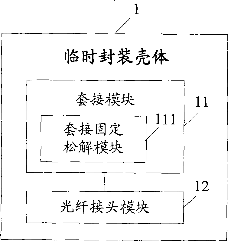
[0034] see figure 1 The schematic structural diagram of the temporary packaging case shown in the embodiment of the present invention, the temporary packaging case 1 includes a socket module 11 and an optical fiber connector module 12, wherein

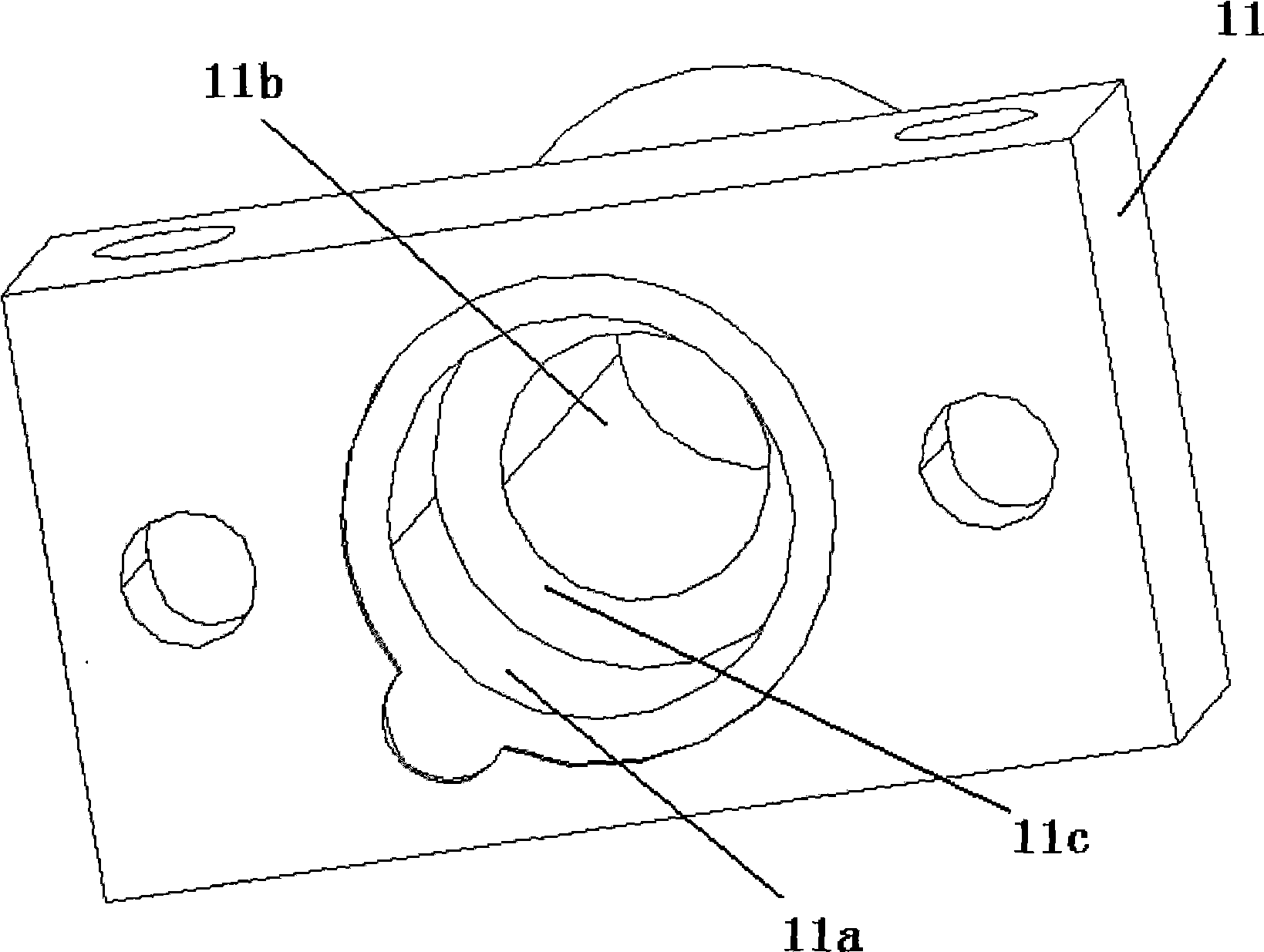
[0035] The socket module 11 is used to socket the photodetector die, and the socket module 11 includes a socket fixing release module 111, which is used to fix or loosen the photodetector die socketed in the socket module 11;

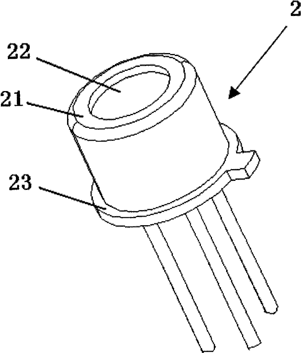
[0036] Specifically, the socket module 11 is socketed on the light-receiving end of the photodetector core; the light-receiving end of the photodetector core has an umbrella edge, and the socket fixing release module 111 can fix or loosen the umbrell...


PUM


Abstract

The embodiment of the invention discloses a method for calibrating the circuit parameters of an optical detector applied to direct coupling. The method includes the following steps: a tube core of the optical detector is sheathed and connected in a temporary encapsulation shell; after receiving optical information through the temporary encapsulation shell, the tube core of the optical detector calibrates the circuit parameters under analog light attenuation; after the calibration of the circuit parameters is completed, the tube core of the optical detector is removed from the temporary encapsulation shell. Correspondingly, the embodiment of the invention also discloses the temporary encapsulation shell. Through the implementation of the embodiment, the tube core of the optical detector is sheathed and connected in the temporary encapsulation shell, and then is removed from the temporary encapsulation shell after the calibration of various circuit parameters is completed to facilitate the final direct coupling, thus realizing the calibration of various circuit parameters in an analog light attenuation way in the process of producing direct coupling products, improving the calibration efficiency of circuit parameters and leading to more convenient and accurate calibration of circuit parameters.

Description

technical field [0001] The invention relates to the communication field, in particular to a method for calibrating the circuit parameters of a directly coupled photodetector and a temporary packaging shell. Background technique [0002] Free Space Optical Communication (FSO, Free Space Optical Communication) often adopts direct coupling to receive the space optical path, that is, the receiving lens directly converges the received light into the photodetector. At present, the packaged photodetector die produced by the photodetector manufacturer is fixed in the housing by non-recoverable fixing methods such as glue or welding, so as to avoid the photodetector die from being subjected to mechanical stress. destroys the internal structure, and can facilitate the calibration of various circuit parameters. However, the packaged photodetector core is generally designed for a certain physical interface for connecting optical fibers. When direct coupling is performed, the package she...

Claims


Application Information

Patent Timeline
Patent Type & Authority Applications(China)
IPC IPC(8): G01J1/44G02B6/36H01L21/56H01L23/28
Inventor 卜建宇
Owner 深圳市新岸通讯技术有限公司
Why Eureka
Try Eureka