Method for rapidly and reliably coupling emission power of light sending and receiving device and coaxial coupling cramp

An optical transceiver device and coupling coaxial technology, which is applied in the field of coupling fixtures, can solve the problems of high manufacturing cost of large fixtures, unreliable glue pre-fixation, and inability to guarantee coaxiality, etc., so as to ensure the yield rate, save cost investment, simple effect design

Inactive Publication Date: 2009-08-19
SUPERXON (CHENGDU) TECH LTD
View PDF0 Cites 9 Cited by
  • Summary
  • Abstract
  • Description
  • Claims
  • Application Information

AI Technical Summary

Problems solved by technology

The disadvantage of this method of pre-fixing with glue and large fixtures is that the manufacturing cost of large fixtures is high and it is inconvenient to disassemble
Dispensing pre-fixation is unreliable and the yield is low
At the same time, due to the weak curing force of the glue, the clamping force arm from the locking point of the large fixture to the welding point is long, so that when laser welding is performed, the instantaneous force will pull the relative position of the

Method used


Image

  • Method for rapidly and reliably coupling emission power of light sending and receiving device and coaxial coupling cramp
  • Method for rapidly and reliably coupling emission power of light sending and receiving device and coaxial coupling cramp
  • Method for rapidly and reliably coupling emission power of light sending and receiving device and coaxial coupling cramp

Examples


Example Embodiment

[0016] Below in conjunction with the best embodiment shown in the accompanying drawings, it will be further described in detail.

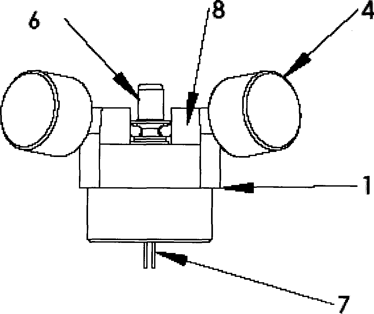
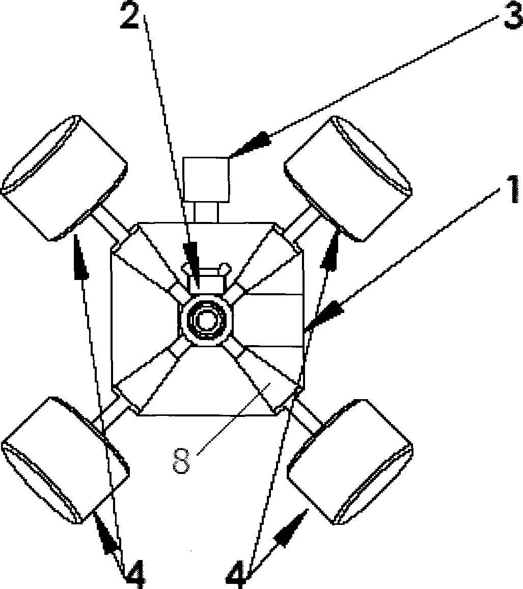
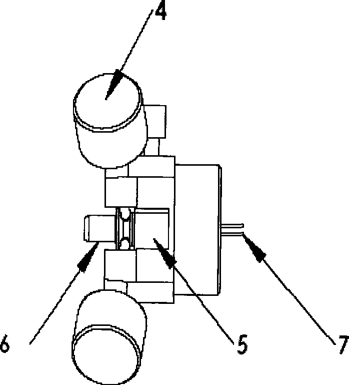
[0017] According to the present invention, a coupling fixture capable of clamping the laser semi-finished product 5 and the optical fiber semi-finished product 6, moving in the X and Y planes and fixing them is prepared. Put the above-mentioned semi-finished laser product 5 to be coupled into the coupling fixture, then put the semi-finished fiber 6 into the corresponding steps of the semi-finished laser, and fix it with four coupling screws. Then transmit power coupling. Through the two opposite screws among the four coupling locking screws 4, the plane movement adjustment in the XY direction is carried out. Start optical power coupling. When the optical power is coupled to the maximum, correspondingly tighten the four coupling screws. Put the coupling fixture and the coupled optical transceiver device into the four-beam laser welding machine fo...


PUM


Abstract

The invention discloses a quick and reliable method for coupling the transmission power of a coaxial light transceiver; the method comprises the following steps: firstly, a coaxial coupling clamp similar to a fort and provided with coupling bolts is prepared; a semi-finished laser and a fiber are clamped in the central locating hole of the coaxial coupling clamp, the bolts are rotatably compressed along the clockwise direction, a pressing block is pushed in, and then the bolts are rotatably coupled along the clockwise direction, thus leading the bolts to be coaxially fixed; power is supplied to an exposed traction angle of the semi-finished laser, and the semi-finished optical fibers are connected to an optical power meter, and then fine adjustment of X axis and Y axis is respectively carried out to two groups of coupling bolts which respectively represent X axis and Y axis, optical power coupling is carried out, and the coupling bolts are fastened when the optical power is coupled to the maximum value. The method has the advantages of simpleness, easy operation, reliable connection, high yield and small clamp body; no change of relative position of the light transceiver in the transportation process, and no loss of light transmission power; low manufacture cost which is one fifteenth of that of the big clamp in the prior art or that of a method of dispensing for pre-fixing; and convenient dismantlement.

Description

technical field [0001] The invention relates to a method for producing and assembling an optical transceiver device in an optical fiber communication system, a method for quickly and reliably coupling the transmission power of the sending end of the optical transceiver device, and a coupling fixture for implementing the method. Background technique [0002] The optical transceiver device in the optical transceiver module is the key device in the optical transceiver module, and the laser emission coupling part of the optical transceiver device is an important process in the production of the optical transceiver device. Generally, the laser semi-finished product and the fiber semi-finished product are fixed with a fixture, and then the three-dimensional coupling table is used for power coupling. Glue is used for pre-fixing, followed by laser welding. or use such as Figure 4 The large fixture with door-type spring guide posts shown, fix the laser semi-finished product and fib...

Claims


Application Information

Patent Timeline
IPC IPC(8): G02B6/42
Inventor 姜先刚邹渊蒋小青
Owner SUPERXON (CHENGDU) TECH LTD
Why Eureka
Try Eureka