LTCC lamination microstrip patch antenna

A microstrip patch antenna and stacking technology, which is applied to the structural form of antennas, electrical components, and radiating elements, can solve the problems of late start of LTCC antennas, improve stability and reliability, reduce section thickness, and enhance coupling Effect

Inactive Publication Date: 2009-08-19
UNIV OF ELECTRONICS SCI & TECH OF CHINA
View PDF0 Cites 43 Cited by
  • Summary
  • Abstract
  • Description
  • Claims
  • Application Information

AI Technical Summary

Problems solved by technology

[0004] At present, due to the late start of the research and design of LTCC antennas, compared with LTCC chip inductors, capacitors, filters and other passive chip devices, the design and manufacture of antennas bas...

Method used


Image

  • LTCC lamination microstrip patch antenna
  • LTCC lamination microstrip patch antenna
  • LTCC lamination microstrip patch antenna

Examples


Embodiment Construction

[0021] The present invention will be further described in detail below in conjunction with the accompanying drawings, but the embodiments of the present invention are not limited thereto.

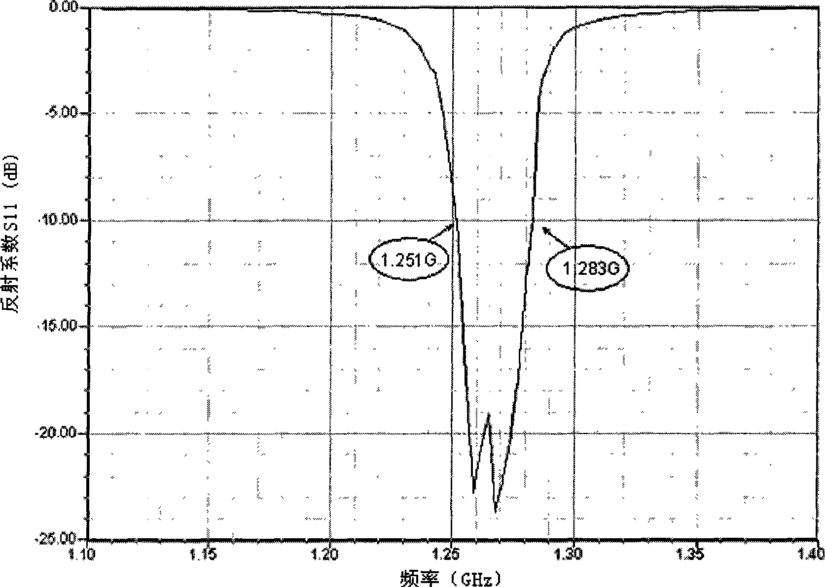
[0022] The center frequency of the microstrip patch antenna in the preferred embodiment is 1.268GHz, and it is a BD-2 microstrip receiving antenna. The present invention can realize a microstrip patch antenna with an impedance bandwidth exceeding 30MHz within a section thickness of 2.5mm.

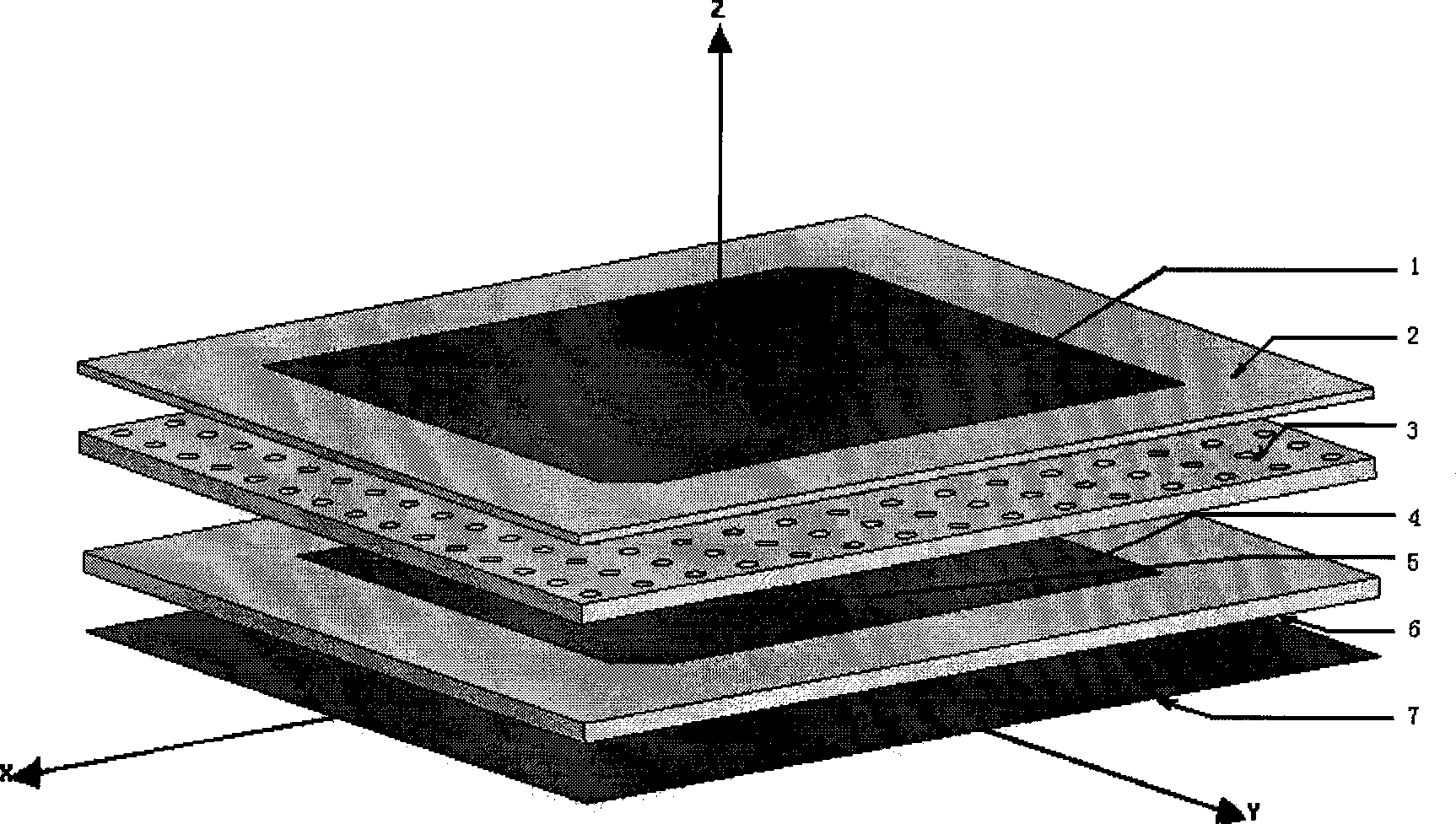
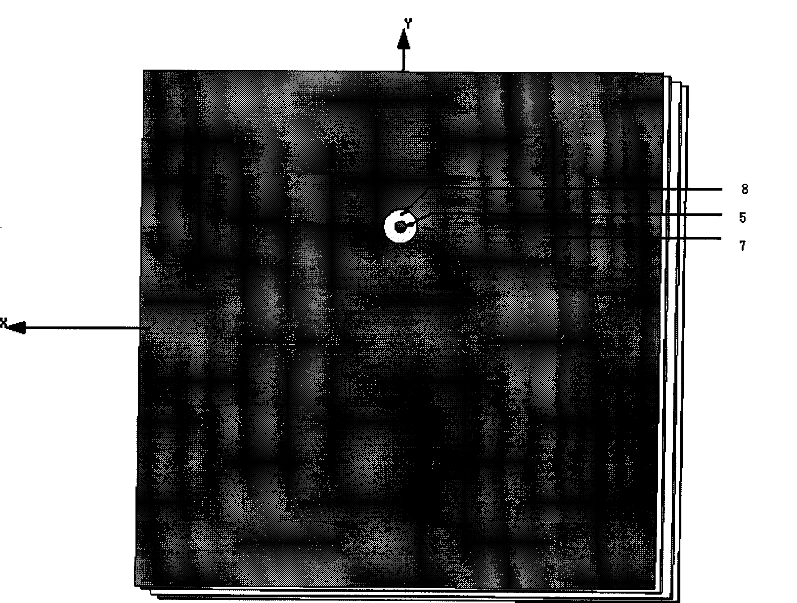
[0023] figure 1 and figure 2 The three-dimensional structural schematic diagram and the bottom view of the LTCC stacked microstrip patch antenna are respectively. The main structures include:

[0024] The first layer of LTCC substrate: It is formed by stacking 10 cast film sheets with a thickness of 0.1mm, and a feed hole with a diameter of about 1mm is opened at an appropriate position on the substrate. The size of the substrate and the position of the feed hole need to be determined by simulating a...


PUM

PropertyMeasurementUnit
Thicknessaaaaaaaaaa
Thicknessaaaaaaaaaa

Abstract

The invention discloses an LTCC-stacked microstrip patch antenna, pertains to the antenna technical field and relates to the LTCC (low temperature co-fired ceramic) technology, in particular to a low profile microstrip patch antenna applied to receiving radio. The microstrip patch antenna comprises three layers of LTCC substrates: the first layer of substrate is provided with a coaxial feeding hole, the upper surface thereof is a first radiation metal patch and the lower surface thereof is a reflection plate; the second layer of substrate is evenly provided with air holes; and the upper surface of the third layer of substrate is a second radiation metal patch. In addition, the microstrip patch antenna also comprises a coaxial feeding needle which is inserted into the coaxial feeding hole from the bottom to be connected with the first radiation metal patch on the first layer of substrate and be insulated with the reflection plate. The first, second and third layers of LTCC substrates form an integrity after passing through an LTCC stack and isostatic pressing technology from the bottom up and co-fire is carried out to the integrity at low temperature so as to form another integrity. The microstrip patch antenna can effectively widen the band width of a microstrip antenna, intensify the coupling between two radiation patches and improve the stability and reliability of the antenna.

Description

technical field [0001] The invention belongs to the technical field of antennas, and relates to low-temperature co-fired ceramic (LTCC) technology, in particular to a low-profile microstrip patch antenna for radio reception. Background technique [0002] Microstrip patch antennas have many advantages such as small size, light weight, thin profile, and easy conformality, and are widely used in wireless communication, remote sensing, aerospace and other fields. However, the narrow working bandwidth of the microstrip patch antenna has also become the bottleneck of its further development. The current microstrip patch antennas generally use organic dielectric materials or ceramic materials as substrates. In order to expand the bandwidth of microstrip patch antennas, common methods include increasing the thickness of the substrate, reducing the dielectric constant of the substrate, adopting a multi-layer structure, and adding impedance. match etc. But these methods are all at t...

Claims


Application Information

Patent Timeline
IPC IPC(8): H01Q1/38H01Q13/08
Inventor 苏桦唐晓莉张怀武徐全吉荆玉兰钟智勇
Owner UNIV OF ELECTRONICS SCI & TECH OF CHINA
Why Eureka
Try Eureka