Grid-proof driving signal oscillation circuit

An oscillation circuit and gate drive technology, applied in the field of anti-gate drive signal oscillation circuit, can solve the problems of reduced MOSFET turn-on speed and the inability of the drive circuit to provide negative voltage, reducing distributed inductance, reducing oscillation amplitude, and simple implementation. Effect

Inactive Publication Date: 2009-08-19
SHANGHAI JIAO TONG UNIV
View PDF0 Cites 8 Cited by
  • Summary
  • Abstract
  • Description
  • Claims
  • Application Information

AI Technical Summary

Problems solved by technology

Its disadvantages are: (a) MOSFET turn-on speed is reduced
(b) The drive circuit cannot provide a certain negative voltage during shutdown

Method used


Image

  • Grid-proof driving signal oscillation circuit

Examples


Embodiment Construction

[0008] Below in conjunction with the accompanying drawings, the embodiments of the present invention are described in detail: the present embodiment is implemented on the premise of the technical solution of the present invention, and provides detailed embodiments and specific descriptions, but the protection scope of the present invention is not limited to the following example.

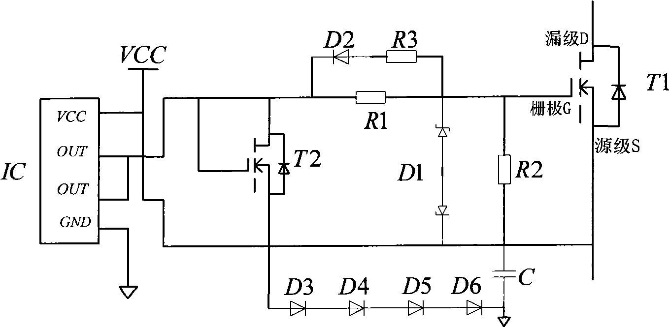
[0009] refer to figure 1 The anti-gate drive signal oscillation circuit involved in this embodiment includes: a drive chip IC, a small gate resistor R1 in series, a high-end switch tube T1, a low-end switch tube T2, a gate-source parallel resistor R2, and a bidirectional Zener diode. D1, current limiting resistor R3, fast recovery diode D2, diode D3, diode D4, diode D5, diode D6, capacitor C. The output signal of the driver chip IC reaches the gate of the high-end switch tube T1 through the gate series small resistor R1, the low-end switch tube T2, the gate-source parallel resistor R2 and the bidir...


PUM


Abstract

The invention relates to an anti-grid driving signal oscillation circuit, which pertains to the electric power technology field and includes a driving chip, a small grid serial resistor, a high-end switching tube, a low-end switching tube, a grid source parallel resistor, a two-way voltage regulator diode, a fast recovery diode, a current-limiting resistor, a diode and a capacitor. The driving chip outputs signals which reach the grids of the high-end switching tube through the small grid serial resistor; the low-end switching tube and the grid source parallel resistor are connected in parallel with the two-way voltage regulator diode; the two ends of the grid source parallel resistor is connected in parallel with a serial branch which is formed by the fast recovery diode and the current-limiting resistor; the positive pole of the fast recovery diode is connected with the current-limiting resistor; a serial branch which is formed by a plurality of diodes and the capacitor is connected in parallel between the source electrode of the low-end switching tube and the grid source parallel resistor; and a reference ground is connected between the diode and the capacitor. The circuit can avoid the direct current of the bridge arm which is produced by the mistaking conduction of MOSFET due to the oscillation of grid driving signals and has the advantages of simple realization, low cost and safety and reliability.

Description

technical field [0001] The invention relates to an oscillating circuit in the technical field of power supply, in particular to an oscillating circuit for preventing gate driving signals. Background technique [0002] Integrated switching power supply and high-frequency induction heating power supply, often using bridge topology MOSFET (metal-oxide film-semiconductor field effect transistor) circuit. In the existing bridge topology MOSFET driving circuit, the Metropolis provides a suitable dead time to prevent the upper and lower switching devices of the same bridge arm from being connected to form a short circuit. However, due to the Miller effect of the drive bridge circuit, the gate drive signal will oscillate during the conversion process of the two power devices on the same bridge arm, and the power device loss is relatively large at this time. When the oscillation amplitude is large, the power device will be turned on, causing the power switch tube to pass through and...

Claims


Application Information

Patent Timeline
Patent Type & Authority Applications(China)
IPC IPC(8): H02M1/36
Inventor 莫锦秋梁庆华王石刚范进秋张斌
Owner SHANGHAI JIAO TONG UNIV
Why Eureka
Try Eureka