Assembling and aligning device and method for thermal infrared spectrum imaging system

A technology of thermal infrared spectroscopy and imaging system, applied in the field of optical instrument installation and calibration technology, can solve problems such as installation and calibration difficulties, and achieve the effect of shortened installation and calibration cycle and strong repeatability

Active Publication Date: 2010-11-17
SHANGHAI INST OF TECHNICAL PHYSICS - CHINESE ACAD OF SCI
View PDF1 Cites 0 Cited by
  • Summary
  • Abstract
  • Description
  • Claims
  • Application Information

AI Technical Summary

Problems solved by technology

At room temperature, the radiation of objects is mainly concentrated in the thermal infrared band, and the radiation of the lens barrel and other objects in the system will form considerable background noise, which will cause great difficulties for installation and calibration at room temperature, and a strong signal source is needed to assist system installation and calibration

Method used


Image

  • Assembling and aligning device and method for thermal infrared spectrum imaging system
  • Assembling and aligning device and method for thermal infrared spectrum imaging system

Examples


Embodiment Construction

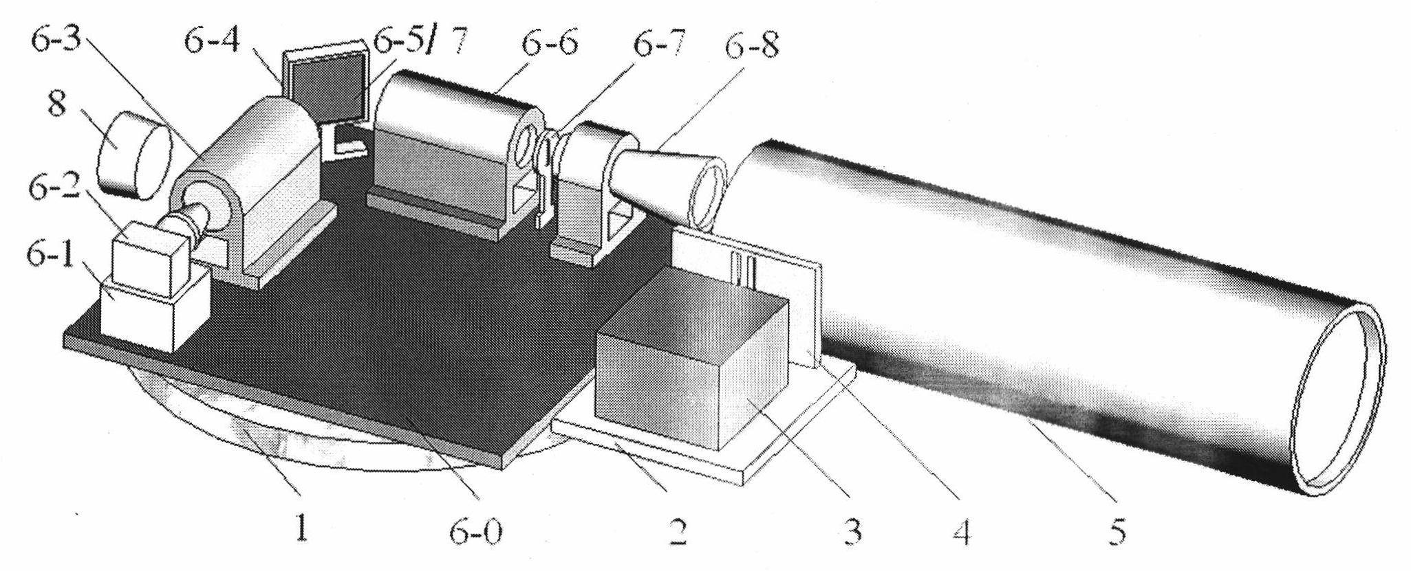
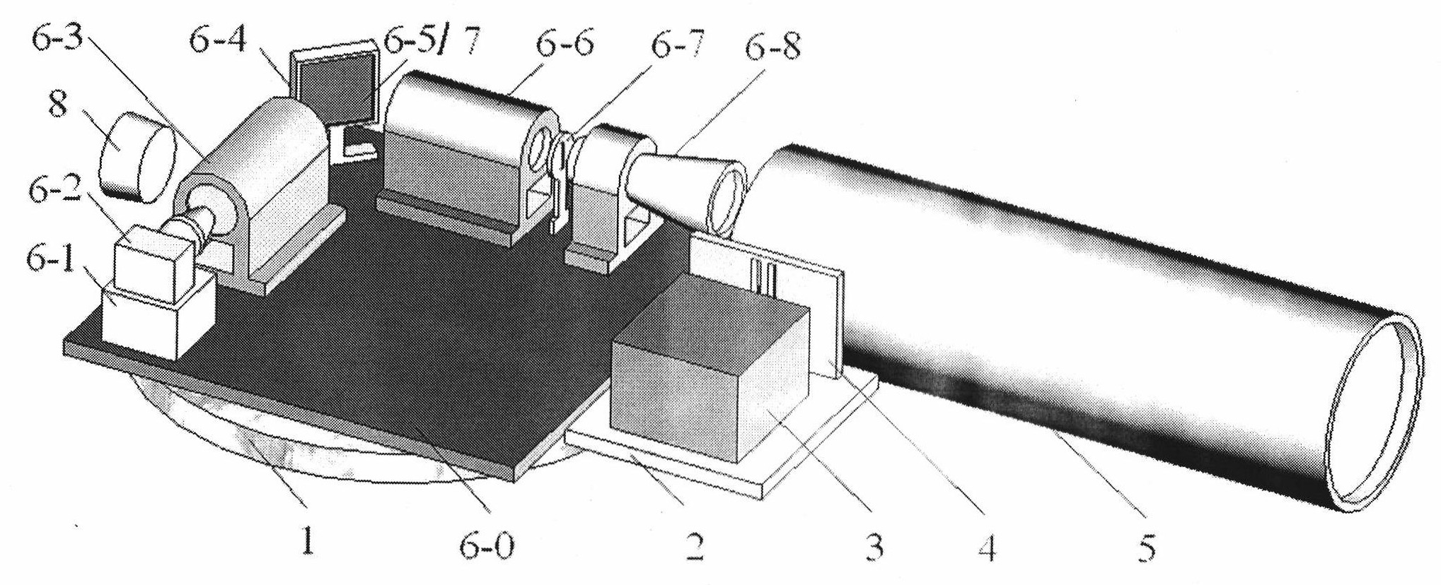
[0038] The following is based on figure 1 Give a preferred embodiment of the present invention and elaborate:

[0039] The focal lengths of the telescopic objective lens, collimating lens and converging lens of the spectral imaging system to be installed are all 40 mm, and a flat reflective blazed grating is used, and the incident angle of the grating at the central working wavelength is θ 2 is 41.8°, the diffraction angle (θ 1 -θ 2 ) is 48.2°, and the optical path between the telephoto lens and the converging lens behind is θ 1 is 90°. The collimator used is a self-developed instrument with a focal length of 4000mm. The detector is an area array detector with a pixel size of 0.03mm. The slit-to-slit width and interval are 4000×0.03 / 40=3mm. The model of the blackbody is HFY-300A from Shanghai Fuyuan Company. The blackbody is on the stage of the collimator, with only a pair of slits in front of it, and the position of the pair of slits is at the focal plane of the collima...


PUM


Abstract

The invention discloses an assembling and aligning method for a thermal infrared spectrum imaging system based on a plane-array detector. As the surface of a lens plated with a thermal infrared anti-rThe invention discloses an assembling and aligning method for a thermal infrared spectrum imaging system based on a plane-array detector. As the surface of a lens plated with a thermal infrared anti-rher common optical instruments, shortens the assembling and aligning period of the system, and has strong repeatability.other common optical instruments, shortens the assembling and aligning period of the system, and has strong repeatability.eflection film has stronger reflection on visible light, the invention provides the assembling and aligning method realized by means of auxiliary objects such as a black body, a slit pair, an auxiliareflection film has stronger reflection on visible light, the invention provides the assembling and aligning method realized by means of auxiliary objects such as a black body, a slit pair, an auxiliary plane mirror, a precision rotary table, an internal focusing telescope, a collimator tube and the like. The method comprises: placing the black body and the slit pair on a focal plane of the collimay plane mirror, a precision rotary table, an internal focusing telescope, a collimator tube and the like. The method comprises: placing the black body and the slit pair on a focal plane of the collimator tube to simulate radiation at infinity, and observing the definition of an image of the slit pair on a photosensitive surface of the detector to determine relative positions of lenses and elementstor tube to simulate radiation at infinity, and observing the definition of an image of the slit pair on a photosensitive surface of the detector to determine relative positions of lenses and elements. The assembling and aligning method can effectively solve the problem that the thermal infrared spectrum imaging system cannot carry out optical assembling and aligning through visual measurement or. The assembling and aligning method can effectively solve the problem that the thermal infrared spectrum imaging system cannot carry out optical assembling and aligning through visual measurement orot

Description

technical field [0001] The invention relates to an optical instrument calibration process technology, in particular to a calibration device and calibration method for a long-wave infrared spectral imaging system, which is also suitable for system calibration of visible near-infrared or mid-wave infrared spectral imaging systems. Background technique [0002] The spectral imaging system can obtain image information and pixel spectral information at the same time, and can directly analyze the material composition of the target from the acquired remote sensing data, so as to effectively identify ground objects, distinguish targets, and expose military camouflage. At present, research on spectral imaging systems in the visible and near-infrared bands is quite common at home and abroad, but research on thermal infrared bands, especially thermal infrared bands above 8 microns, and finely divided spectral imaging systems is still relatively small. Compared with foreign countries, o...

Claims


Application Information

Patent Timeline
Patent Type & Authority Patents(China)
IPC IPC(8): G01J5/10
Inventor 袁立银林颖王建宇徐卫明舒嵘
Owner SHANGHAI INST OF TECHNICAL PHYSICS - CHINESE ACAD OF SCI
Why Eureka
Try Eureka