
Time interval measuring instrument based on FPGA

A technology of time interval measurement and virtual instrument, which is applied in the direction of electrical unknown time interval measurement, devices and instruments for measuring time interval, etc., can solve the problems of less measurement channels, low integration, poor reliability and anti-interference, etc., to achieve The effect of improving measurement efficiency, strong scalability, and high reliability

Inactive Publication Date: 2009-09-02
INST OF FLUID PHYSICS CHINA ACAD OF ENG PHYSICS
View PDF1 Cites 39 Cited by
  • Summary
  • Abstract
  • Description
  • Claims
  • Application Information

AI Technical Summary

Problems solved by technology

However, with the development of technology and the higher and higher requirements of experiments, the time interval measuring instrument still needs further improvement. First, its serial interface cannot meet the requirements of test system automation; second, most of the circuit parts are discrete components. The integration level is not high, so the structure is complicated, the installation is inconvenient, and the reliability needs to be improved; the third is that the chassis is too heavy, the strength is not enough, the load-bearing capacity is poor, and it is inconvenient to disassemble, which brings difficulties to maintenance
[0003] Chinese Patent Literature Publication No. 101013304A discloses a patent application technology named "A PCI Card for High-precision Time Interval Measurement". This technology has fewer measurement channels and poor scalability due to the use of a dedicated chip; due to the use of PCI as the data interface , poor reliability and anti-interference, not suitable for occasions with high measurement requirements such as high reliability and multi-channel

Method used


Image

  • Time interval measuring instrument based on FPGA
  • Time interval measuring instrument based on FPGA
  • Time interval measuring instrument based on FPGA

Examples


Embodiment Construction

[0017] The present invention will be further described in detail below in conjunction with the accompanying drawings and embodiments.

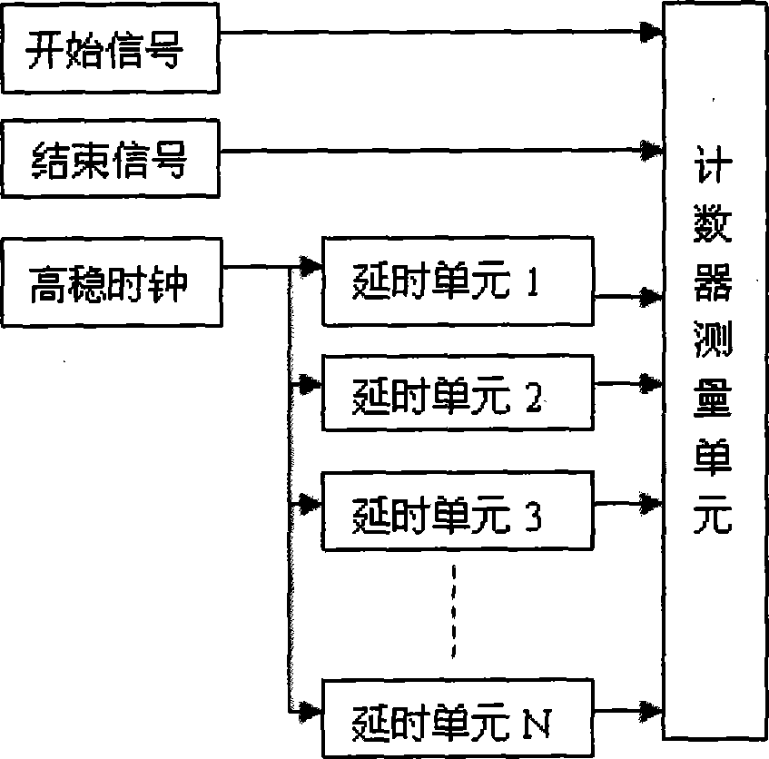
[0018] figure 1 It is a time-delay quantization method for improving measurement resolution of an FPGA-based time interval measuring instrument of the present invention-hour hand phase separation. Methods for accurately measuring time intervals include direct counting, interpolation, and time-to-voltage transformation. From the perspective of keeping the structure as simple as possible while taking into account the measurement accuracy, the present invention adopts a time interval measurement method based on delay line technology—quantized time delay method. The quantitative delay method is developed with the application of large-scale integrated circuits in recent years. It is a method to measure the signal or clock separately after a certain delay, so as to improve the measurement accuracy. The realization of the idea of ​​quantized delay ...


PUM


Abstract

The invention provides a time interval measuring instrument based on FPGA. The time interval measuring instrument is designed into a virtual instrument by taking a PXI interface as a platform; a PXI system can be inserted with a plurality of PXI cards; each card carries out time interval measurement to signals of one initial channel and a plurality of stopping channels; simultaneously the pulse width of stop pulse is measured. The time interval measuring instrument utilizes phase-locked loop frequency doubling and time phase-splitting technology so that the measuring resolution can be up to 1ns and the measuring range can be up to 20ns to 200ms. As the virtual instrument structure is adopted, a PXI platform and a computer are combined to form an automatic measuring system; and the time interval measuring instrument has the advantages of simple structure, convenient use, high reliability, strong expandability and high measuring efficiency.

Description

technical field [0001] The invention belongs to the technical field of data acquisition, and in particular relates to an FPGA-based time interval measuring instrument for measuring the time interval between a start pulse and multiple stop pulses and the pulse width of the stop pulses. Background technique [0002] Precision time interval measurement is widely used in various scientific experiments. Instruments used for time interval measurement include general-purpose counters, digital storage oscilloscopes, and multi-channel time interval measuring instruments have their own characteristics. General-purpose counters are expensive, inconvenient to operate, and have few measurement channels, and have gradually withdrawn from the occasion of time interval measurement. Oscilloscopes have always occupied the main position in electronic measuring instruments, but when the number of independent test points reaches dozens or hundreds, the number of channels of the oscilloscope is t...

Claims


Application Information

Patent Timeline
IPC IPC(8): G04F10/00G04F10/04
Inventor 叶超冯莉
Owner INST OF FLUID PHYSICS CHINA ACAD OF ENG PHYSICS
Learn More