Method for equivalence hinged corrugated pipe by coupled variable cross-section beam

A technology of variable cross-section beams and design methods, which can be used in calculations, special data processing applications, instruments, etc., and can solve problems such as difficulty in calculation and debugging.

Inactive Publication Date: 2009-09-02
TSINGHUA UNIV
View PDF0 Cites 13 Cited by
  • Summary
  • Abstract
  • Description
  • Claims
  • Application Information

AI Technical Summary

Problems solved by technology

[0003] The present invention proposes a design method in which the real hinged bellows is equivalent to two coupled variable-section beams, which well solves the problem that the finite element calculation and debugging of the hinged bellows pipeline system is difficult

Method used


Image

  • Method for equivalence hinged corrugated pipe by coupled variable cross-section beam
  • Method for equivalence hinged corrugated pipe by coupled variable cross-section beam
  • Method for equivalence hinged corrugated pipe by coupled variable cross-section beam

Examples


Embodiment Construction

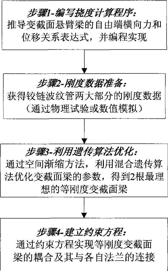
[0079] as attached figure 1 According to the steps of implementing the invention, the present invention includes the following four parts: 1) deriving the expression of the relationship between the lateral force and the displacement at the free end of the variable-section beam of the cantilever; 2) simplifying the hinged bellows, and obtaining the real Stiffness data of the two parts of the hinge bellows; 3) Using the hybrid genetic algorithm to optimize the parameters of each variable-section beam to obtain two variable-section beams with equal stiffness in the transverse direction; 4) Given the coupling of the variable-section beam and its connection with the flange method. The following four parts are introduced respectively.

[0080] 1 The relationship between lateral force and displacement of beam with small deflection and variable cross-section

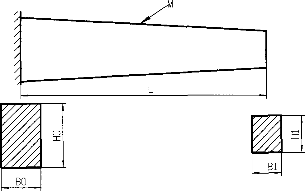
[0081] 1.1 Geometric parameters of variable cross-section beams

[0082] Instructions attached figure 2 Five geometric p...


PUM


Abstract

The invention relates to a design method for the equivalence a hinged corrugated pipe by coupled variable cross-section beams in order to simplify the finite element analysis work for the complicated pipeline system design of the hinged corrugated pipe. Firstly, deducing the relation between force and displacement when transversal force is exerted on the free end of either variable cross-section beam of which any interface is rectangular based on the assumption that a cantilever beam has small deflection, and considering the elasticity and the elastic plastic deformation of either variable cross-section beam; secondly, proposing a method of simplifying a hinged corrugated pipe model and a method of utilizing finite element calculation to obtain the rigidity data of the fixed part of the simplified hinged corrugated pipe in two directions; thirdly, proposing a method of utilizing a mixing genetic algorithm to optimize parameters of the variable cross-section beams and proposing a special gradual shrinkage method aiming at the mixing genetic algorithm so as to further obtain geometric parameters and material parameters of the two variable cross-section beams; and finally, coupling the two variable cross-section beams at the free ends by constraint equations and connecting the roots of the variable cross-section beams with flanges by establishing auxiliary discs.

Description

technical field [0001] The invention relates to a design method for using coupled variable-section beams to replace hinge bellows in finite element analysis of pipeline systems. The finite element analysis work of complex piping system with hinged bellows can be simplified by using the equivalent variable cross-section beam. Background technique [0002] In large-span complex pipeline systems, hinged bellows are usually used to absorb the angular displacement at the pipeline joints, but it is also unavoidable to withstand certain lateral displacements. The structure of the hinge bellows is relatively complex, including flanges at both ends, corrugations, rings, single lugs, double lugs, rivets, gaskets, joints and other parts. There are 10 contacts in the hinge bellows structure, such as rings Between the rivet and the lug, between the rivet and the lug, etc., if the hinge bellows are not simplified or equivalent when the finite element method is used to analyze the respons...

Claims


Application Information

Patent Timeline
Patent Type & Authority Applications(China)
IPC IPC(8): G06F17/50
Inventor 赵加清曾攀雷丽萍
Owner TSINGHUA UNIV
Why Eureka
Try Eureka