Heat exchanger and refrigeration device
A technology for heat exchangers and refrigeration devices, applied in the field of refrigeration devices and heat exchangers, can solve problems such as poor compatibility and reduced heat transfer performance, and achieve the effects of increasing contact area, promoting heat transfer, and ensuring the amount of oil returned
- Summary
- Abstract
- Description
- Claims
- Application Information
AI Technical Summary
Problems solved by technology
Method used
Image
Examples
no. 1 approach 》
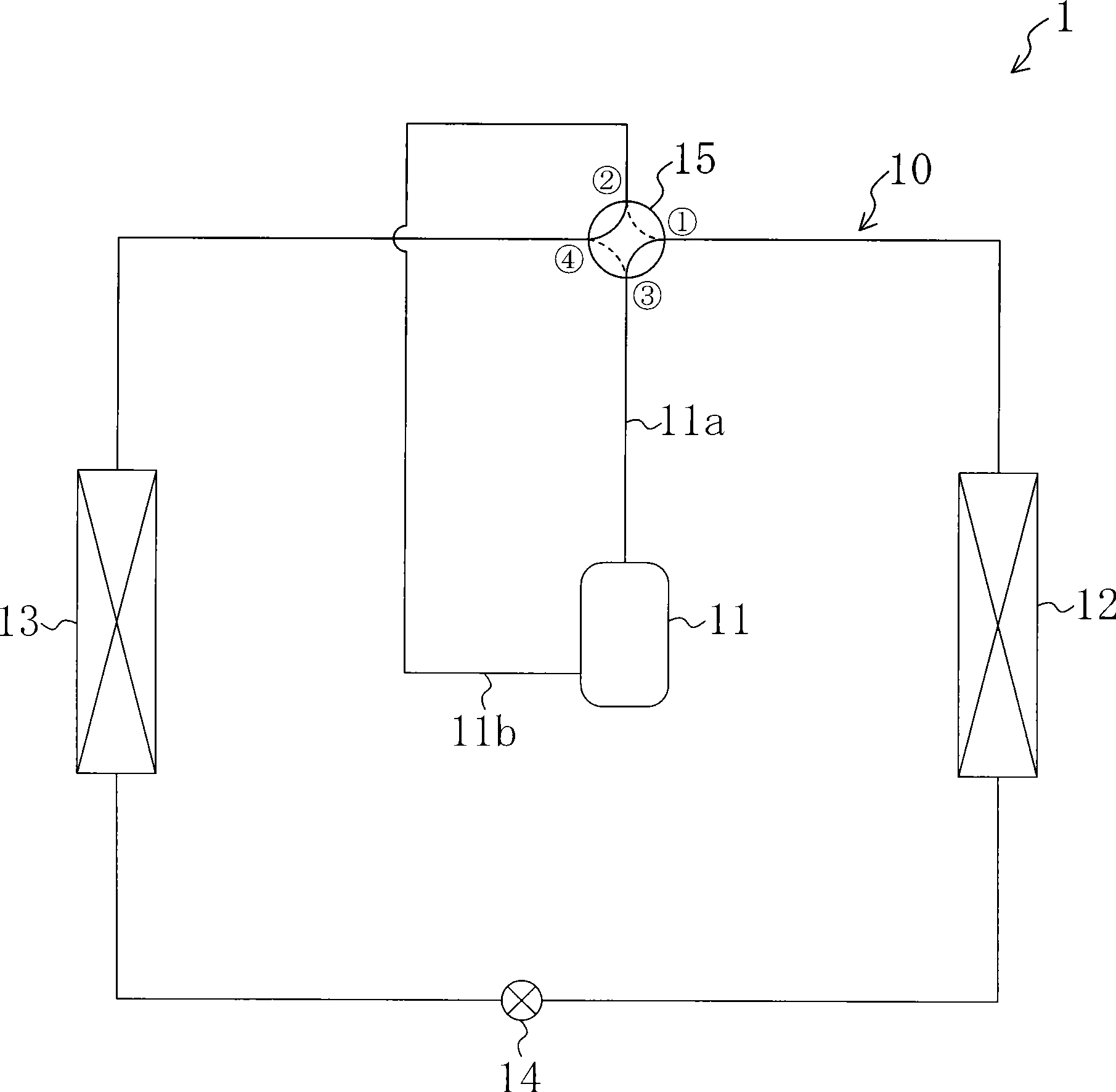
[0075] The heat exchanger according to the first embodiment of the present invention is used in a refrigeration device 1 that performs a vapor compression refrigeration cycle. The refrigeration system according to the first embodiment constitutes an air conditioner 1 capable of switching between indoor cooling and heating.
[0076]
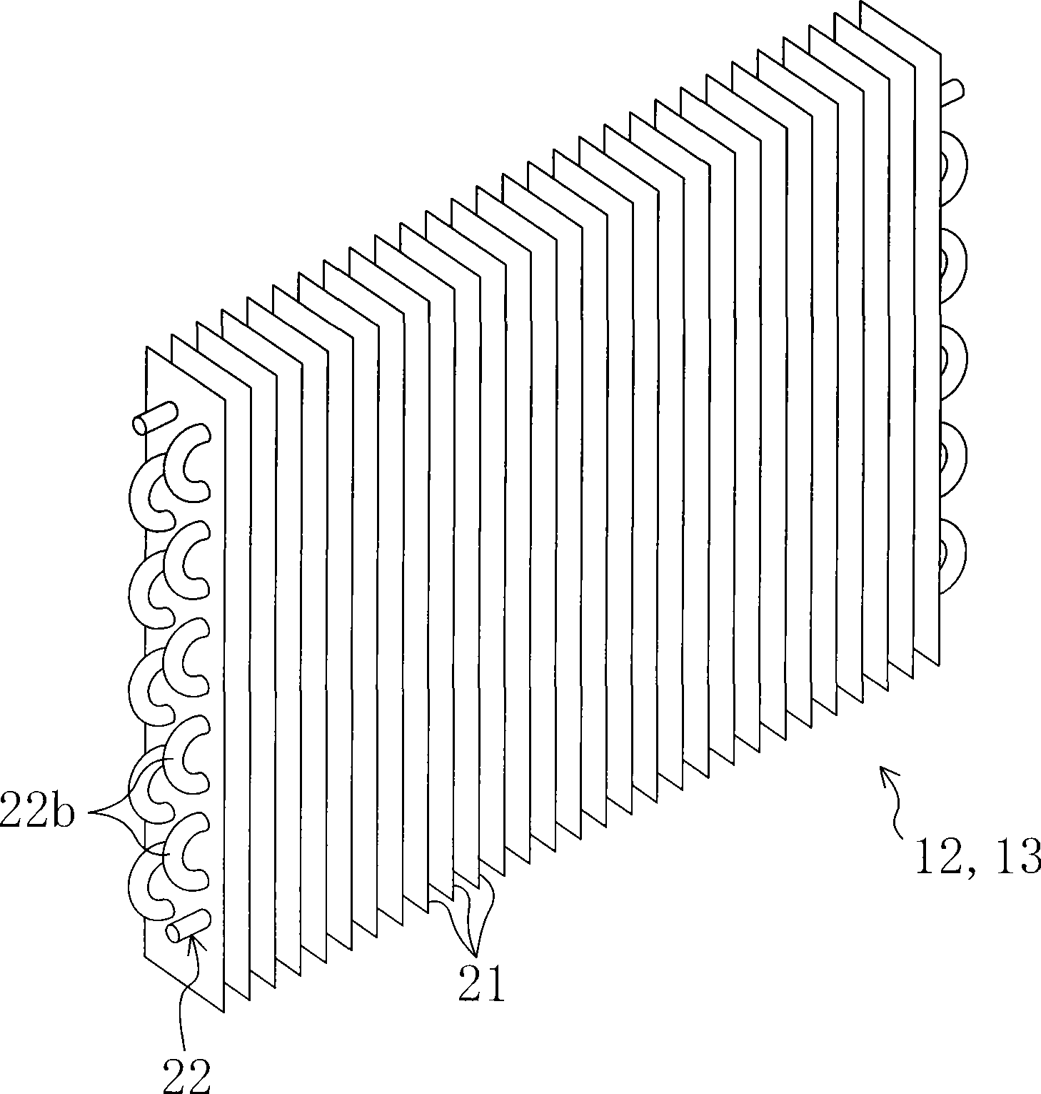
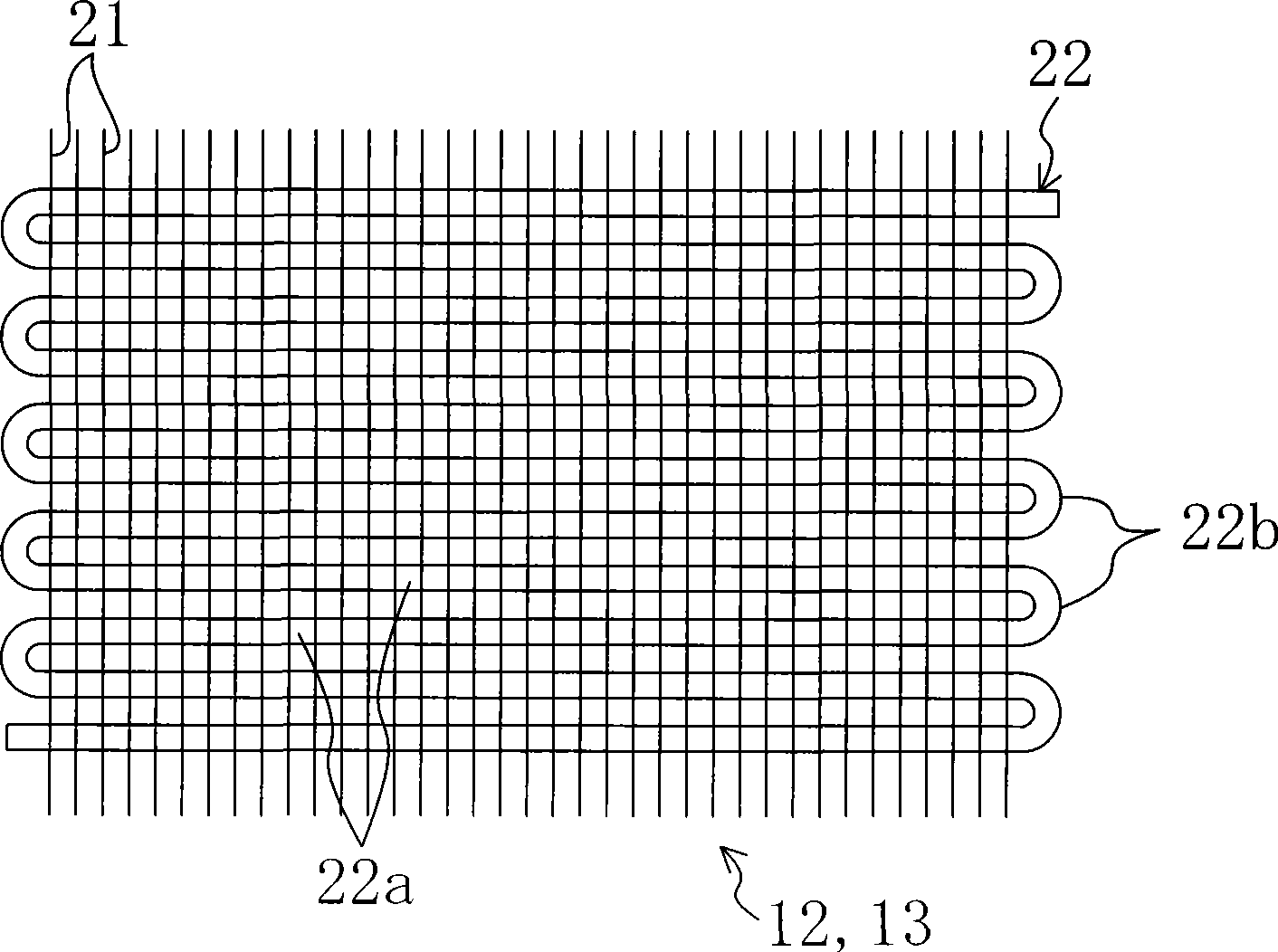
[0077] like figure 1 As shown, the air conditioning device 1 includes a refrigerant circuit 10 filled with refrigerant. The refrigerant circuit 10 is filled with carbon dioxide as a refrigerant. In this air conditioner 1, polyalkylene glycol (PAG), which is a polar oil, acts as lubricating oil (refrigerating machine oil) for lubricating each sliding portion of the compressor 11 . And, this PAG flows into the refrigerant circuit 10 together with the refrigerant discharged from the compressor 11 . Therefore, in the refrigerant circuit 10, carbon dioxide as a refrigerant and PAG as refrigerating machine oil circulate together. In addition, in t...
no. 2 approach 》
[0097] In the heat exchangers 12 and 13 according to the second embodiment of the present invention, the structure of the heat transfer tube 22 is different from that of the first embodiment. Specifically, as Figure 7 As shown, a plurality of oil grooves 25 are formed in the heat transfer tube 22 of the second embodiment, and the number of the oil grooves 25 is more than that of the first embodiment. Similar to the first embodiment, the oil groove 25 extends in the axial direction of the heat transfer tube 22 .
[0098] In addition, in the second embodiment, the lipophilic layer 27 made of lipophilic material is formed on the bottom surface 25b of the oil groove 25 by surface coating. In addition, examples of lipophilic materials constituting the lipophilic layer 27 include water glass, acrylic, epoxy resin, polyvinyl alcohol, and the like. On the other hand, an oil-repellent layer 28 made of an oil-repellent material is formed on the entire inner wall surface of the heat t...
no. 3 approach 》
[0105] In the heat exchangers 12 and 13 according to the third embodiment of the present invention, the structure of the heat transfer tube 22 is different from the above-mentioned first and second embodiments. Specifically, as Figure 9As shown, a plurality of oil grooves 25 extending in a “V” shape are formed on the inner wall surface of the heat transfer tube 22 of the third embodiment. The V-shaped oil groove 25 is formed by connecting the top ends of a pair of grooves 25c, 25c inclined to the axial direction of the heat transfer tube 22 . In addition, each oil groove 25 is arranged in the axial direction of the heat transfer tube 22, and is spaced apart from each other at predetermined intervals. In addition, in each oil groove 25 , a “V”-shaped tip portion 25 d formed by connecting a pair of grooves 25 c and 25 c faces the refrigerant outflow side of the heat transfer tube 22 . That is, the “V”-shaped top ends 25d of the respective oil grooves 25 are directed to the sa...
PUM
 Abstract
Description
Claims
Application Information
 - R&D
- Intellectual Property
- Life Sciences
- Materials
- Tech Scout
- Unparalleled Data Quality
- Higher Quality Content
- 60% Fewer Hallucinations
Browse by: Latest US Patents, China's latest patents, Technical Efficacy Thesaurus, Application Domain, Technology Topic, Popular Technical Reports.
© 2025 PatSnap. All rights reserved.Legal|Privacy policy|Modern Slavery Act Transparency Statement|Sitemap|About US| Contact US: help@patsnap.com


